DESCRIPTION |
Detection Item | Symptom |
Trouble Area | | Suspension Control ECU Communication Stop Mode |
Any of the following conditions are met:
- Communication stop for "Suspension Control (Air Suspension)" is
indicated on the "Communication Bus Check" screen of the Techstream.
Click here 
- Communication stop history for "Suspension Control (Air Suspension)" is
indicated on the "Communication Bus Check (Detail)" screen of the
Techstream. (The Lost Communication Time value for "Suspension Control
(Air Suspension)" is 6 or more.)
Click here
- Communication system DTCs (DTCs that start with U) that correspond to
"Suspension Control ECU Communication Stop Mode" in "DTC Combination
Table" are output.
Click here
|
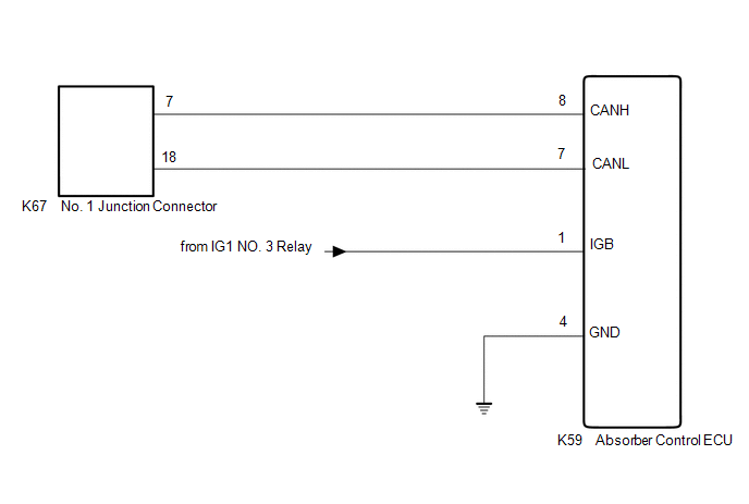
- Absorber control ECU CAN branch line or connector
- Power source circuit of absorber control ECU
- Absorber control ECU ground circuit
- Absorber control ECU
| WIRING DIAGRAM
 CAUTION / NOTICE / HINT
CAUTION: When performing the confirmation driving pattern, obey all speed limits and traffic laws.
NOTICE:
HINT:
- Before disconnecting related connectors for inspection, push in on each
connector body to check that the connector is not loose or disconnected.
- When a connector is disconnected, check that the terminals and connector body are not cracked, deformed or corroded.
PROCEDURE |
1. | CHECK FOR OPEN IN CAN BUS LINES (ABSORBER CONTROL ECU BRANCH LINE) |
(a) Disconnect the cable from the negative (-) battery terminal.
| (b) Disconnect the K59 absorber control ECU connector. |
 |
|
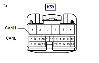
*a | Front view of wire harness connector
(to Absorber Control ECU) | | |
(c) Measure the resistance according to the value(s) in the table below.
Standard Resistance: |
Tester Connection | Condition |
Specified Condition | |
K59-8 (CANH) - K59-7 (CANL) |
Cable disconnected from negative (-) battery terminal |
54 to 69 Ω |
| NG |
 | REPAIR OR REPLACE CAN BRANCH LINES OR CONNECTOR (ABSORBER CONTROL ECU) |
|
OK |
 | |
| 2. |
CHECK HARNESS AND CONNECTOR (POWER SOURCE CIRCUIT) |
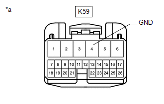
| (a) Measure the resistance according to the value(s) in the table below.
Standard Resistance: |
Tester Connection | Condition |
Specified Condition | |
K59-4 (GND) - Body ground |
Cable disconnected from negative (-) battery terminal |
Below 1 Ω | |
 |
|
*a | Front view of wire harness connector
(to Absorber Control ECU) | | |
(b) Reconnect the cable to the negative (-) battery terminal.
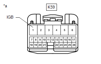
| (c) Measure the voltage according to the value(s) in the table below.
Standard Voltage: |
Tester Connection | Switch Condition |
Specified Condition | |
K59-1 (IGB) - Body ground |
Engine switch on (IG) |
11 to 14 V | |
 |
|
*a | Front view of wire harness connector
(to Absorber Control ECU) | | |
| OK |
| REPLACE ABSORBER CONTROL ECU |
| NG |
| REPAIR OR REPLACE HARNESS OR CONNECTOR (POWER SOURCE CIRCUIT) | |


