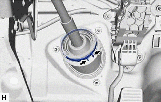
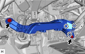
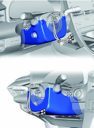
INSTALLATION PROCEDURE 1. ALIGN FRONT WHEELS FACING STRAIGHT AHEAD 2. INSTALL STEERING COLUMN ASSEMBLY NOTICE: Make sure that the wire harness is not interfering with the steering column assembly. (a) Install the steering column assembly with the bolt and 2 nuts. Torque: 36 N·m {367 kgf·cm, 27 ft·lbf} (b) Connect each connector and engage each wire harness clamp to the steering column assembly. 3. INSTALL STEERING INTERMEDIATE SHAFT ASSEMBLY (a) Align the matchmarks on the steering intermediate shaft assembly and steering column assembly. 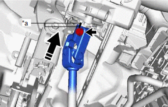
(b) Install the steering intermediate shaft assembly to the steering column assembly. (c) Install the bolt. Torque: 35 N·m {357 kgf·cm, 26 ft·lbf}
4. INSTALL STEERING COLUMN HOLE COVER (a) Install the steering column hole cover with the 2 clips. (b) Install the clip. (c) Return the floor carpet. 5. CONNECT STEERING INTERMEDIATE SHAFT ASSEMBLY (for Gasoline Model) Click here 6. CONNECT STEERING INTERMEDIATE SHAFT ASSEMBLY (for HV Model) Click here 7. INSTALL FRONT WHEEL LH Click here 8. INSTALL NO. 1 AIR DUCT
(b) Install the 2 bolts. Torque: 9.8 N·m {100 kgf·cm, 87 in·lbf} 9. INSTALL LOWER NO. 1 INSTRUMENT PANEL AIRBAG ASSEMBLY Click here
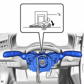
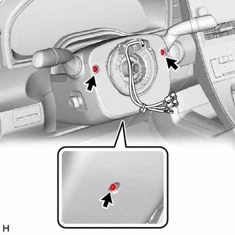
10. INSTALL TURN SIGNAL SWITCH ASSEMBLY WITH SPIRAL CABLE SUB-ASSEMBLY NOTICE:
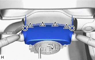
(b) While holding the clamp expanded, install the turn signal switch assembly with spiral cable sub-assembly to the steering column assembly and engage the claw. (c) Return the clamp to its original position. (d) Connect the connectors to the turn signal switch assembly with spiral cable sub-assembly. 11. INSTALL UPPER STEERING COLUMN COVER
(b) Engage the claw to install the upper steering column cover. 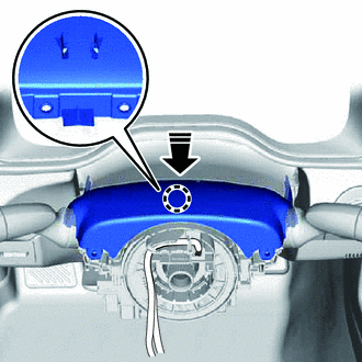
12. INSTALL LOWER STEERING COLUMN COVER
13. ALIGN FRONT WHEELS FACING STRAIGHT AHEAD 14. INSPECT AND ADJUST SPIRAL CABLE WITH SENSOR SUB-ASSEMBLY Click here 15. INSTALL STEERING WHEEL ASSEMBLY Click here 16. CHECK STEERING WHEEL CENTER POINT 17. INSTALL HORN BUTTON ASSEMBLY Click here
18. CUSTOMIZE POWER TILT AND POWER TELESCOPIC STEERING COLUMN SYSTEM (a) Set the auto tilt away function setting to the previous condition by changing the customize parameter. for Gasoline Model: Click here for HV Model: Click here
19. PERFORM INITIALIZATION AND CALIBRATION (for Gasoline Model) for Parking Assist Monitor System Initialization: Click here
for Parking Assist Monitor System Calibration: Click here
for Panoramic View Monitor System Initialization: Click here
for Panoramic View Monitor System Calibration: Click here
for Intelligent Clearance Sonar System Calibration: Click here
20. PERFORM INITIALIZATION AND CALIBRATION (for HV Model) for Parking Assist Monitor System Initialization: Click here
for Parking Assist Monitor System Calibration: Click here
for Panoramic View Monitor System Initialization: Click here
for Panoramic View Monitor System Calibration: Click here
for Intelligent Clearance Sonar System Calibration: Click here
|
Toyota Avalon (XX50) 2019-2022 Service & Repair Manual > Motor Generator Control System: DC/DC Converter Voltage Sensor "A"(VL) Circuit Voltage Above Threshold (P0E5717)
DTC SUMMARY MALFUNCTION DESCRIPTION If an overvoltage malfunction occurs in the motor inverter or generator inverter, the motor generator control ECU (MG ECU) detects the malfunction and stores this DTC. The cause of this malfunction may be one of the following: Area Main Malfunction Description Hyb ...