REASSEMBLY PROCEDURE 1. INSTALL NO. 2 STEERING RACK BOOT (a) Apply lithium soap base glycol grease to the inside of the small opening of a new No. 2 steering rack boot. 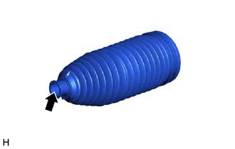
(b) Install the No. 2 steering rack boot to the groove on the rack housing. NOTICE:
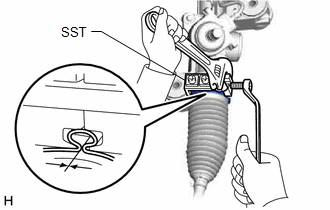
2. INSTALL NO. 1 STEERING RACK BOOT HINT: Perform the same procedure as for the No. 2 steering rack boot. 3. INSTALL NO. 2 STEERING RACK BOOT CLAMP (for LH Side) (a) Temporarily install a new No. 2 steering rack boot clamp to the No. 2 steering rack boot. NOTICE: Do not damage the No. 2 steering rack boot. HINT: The protrusion of the No. 2 steering rack boot clamp can be installed at any position.
(c) Remove SST and measure the clearance of the No. 2 steering rack boot clamp. Clearance: 2.5 to 4.0 mm (0.0984 to 0.157 in.) 4. INSTALL NO. 2 STEERING RACK BOOT CLAMP (for RH Side) HINT: Perform the same procedure as for the LH side. 5. INSTALL STEERING RACK BOOT CLIP (for LH Side) (a) Using pliers, install the steering rack boot clip. 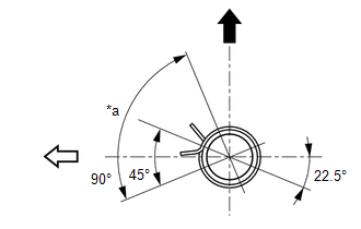
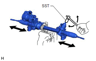
HINT: Make sure that the tabs of the steering rack boot clip are positioned within the area shown in the illustration. 6. INSTALL STEERING RACK BOOT CLIP (for RH Side) HINT: Perform the same procedure as for the LH side. 7. INSPECT RACK AND PINION POWER STEERING GEAR ASSEMBLY
|
Toyota Avalon (XX50) 2019-2022 Service & Repair Manual > Can Communication System(for Hv Model): Check Bus 3 Line for Short to GND
DESCRIPTION There may be a short circuit between one of the CAN bus lines and GND when there is no resistance between terminal 6 (CA3H) of the central gateway ECU (network gateway ECU) and terminal 4 (CG) of the DLC3, or terminal 21 (CA3L) of the central gateway ECU (network gateway ECU) and termina ...