REMOVAL CAUTION / NOTICE / HINT
The
necessary procedures (adjustment, calibration, initialization, or
registration) that must be performed after parts are removed and
installed, or replaced during front lower ball joint assembly
removal/installation are shown below. Necessary Procedures After Parts Removed/Installed/Replaced (for HV Model:) |
Replaced Part or Performed Procedure |
Necessary Procedure | Effect/Inoperative Function when Necessary Procedure not Performed |
Link | |
*: When performing learning using the Techstream.
Click here  | |
Auxiliary battery terminal is disconnected/reconnected |
Perform steering sensor zero point calibration |
Lane Departure Alert System (w/ Steering Control) |
| |
Pre-collision System | |
Intelligent Clearance Sonar System* | |
Lighting System (for HV Model with Cornering Light) | |
Memorize steering angle neutral point |
Parking Assist Monitor System |
| |
Panoramic View Monitor System |
| |
Front wheel alignment adjustment |
- Clear zero point calibration data.
- Perform yaw rate and acceleration sensor zero point calibration.
|
- DTCs are stored
- ABS warning light illuminates
- Brake warning light / yellow (minor malfunction) illuminates
- Slip indicator light illuminates
- VSC disabled or malfunctions
|
| Necessary Procedures After Parts Removed/Installed/Replaced (for Gasoline Model:) |
Replaced Part or Performed Procedure |
Necessary Procedure | Effect/Inoperative Function when Necessary Procedure not Performed |
Link | | Front wheel alignment adjustment |
Perform system variant learning and acceleration sensor zero point calibration. |
- VSC disabled or malfunctioning
- DTCs are output
- Slip indicator light illuminated
- ABS warning light illuminated
|
| for HV Model:
- When removing or installing the front disc brake caliper assembly,
pushing back the disc brake piston may cause a large clearance between
the brake pads and brake disc. When the brake pedal is depressed with a
large clearance between the brake pads and the brake disc, DTC C1214
related to abnormal brake fluid pressure may be stored. Make sure to
clear any DTCs after performing this procedure.
- While the auxiliary battery is connected, even if the power switch is
off, the brake control system activates when the brake pedal is
depressed or any door courtesy switch turns on. Therefore, when
servicing the brake system components, do not operate the brake pedal or
open/close the doors while the auxiliary battery is connected.
HINT:
- Use the same procedure for the RH side and LH side.
- The following procedure is for the LH side.
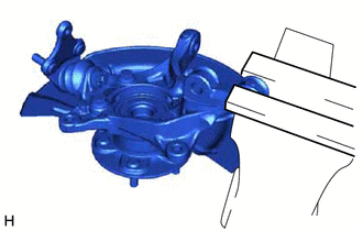
PROCEDURE 1. REMOVE FRONT AXLE ASSEMBLY
Click here 2. REMOVE FRONT LOWER BALL JOINT ASSEMBLY
| (a) Secure the front axle assembly in a vise using aluminum plates.
NOTICE: Do not overtighten the vise. | |
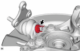
| (b) Remove the cotter pin. | |
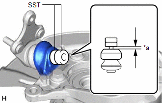
(c) Remove the nut. | (d) Install SST to the front lower ball joint assembly as shown in the illustration.
SST: 09960-20010 09961-02050 NOTICE: Check that the clearance measurement between SST and the front axle assembly is 1 mm (0.0394 in.). |
|
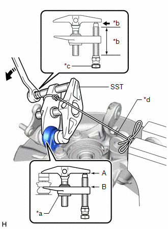
(e) Using SST, remove the front lower ball joint assembly from the front axle assembly as shown in the illustration.
SST: 09960-20010 09961-02010 09961-02050
|
*a | Center Nut | |
*b | Molybdenum Grease Application Area | |
*c | Place wrench here | |
*d | String |
 |
Turn | CAUTION: Apply molybdenum grease to the threads and end of the SST bolt.
NOTICE:
- Be sure to tighten the string firmly to secure SST to the front axle assembly to prevent SST from falling off.
- Install SST with the center nut so that (A) and (B) shown in the
illustration are parallel. Otherwise, the front lower ball joint dust
cover may be damaged.
- Be sure to place a wrench on the part shown in the illustration.
- Do not damage the front lower ball joint dust cover.
- Do not damage the steering knuckle.
- Do not damage the front disc brake dust cover.
|