REMOVAL CAUTION / NOTICE / HINT
The
necessary procedures (adjustment, calibration, initialization, or
registration) that must be performed after parts are removed and
installed, or replaced during front frame assembly removal/installation
are shown below. Necessary Procedure After Parts Removed/Installed/Replaced |
Replaced Part or Performed Procedure |
Necessary Procedure | Effect/Inoperative Function when Necessary Procedure not Performed |
Link | |
Battery terminal is disconnected/reconnected |
Perform steering sensor zero point calibration |
Lane departure alert system (w/ Steering Control) |
 | |
Pre-collision system | |
Intelligent clearance sonar system*1 | |
Lighting system (for Gasoline Model with Cornering Light) | |
Memorize steering angle neutral point |
Parking assist monitor system |
| |
Panoramic view monitor system |
| |
Replacement of ECM | Vehicle Identification Number (VIN) registration |
MIL comes on |
| |
Perform code registration (Immobiliser system) |
Engine start function |
|
- Replacement of engine assembly
- Gas leak from exhaust system is repaired
| Inspection after repair |
- Poor idle, etc.
- Engine start function, etc.
|
| |
Replacement of automatic transaxle assembly |
- Reset Memory
- Input transaxle compensation code into ECM
- Perform road test to allow ECM to learn
|
- Large shift shock
- Deterioration of fuel efficiency
| for Initialization:
for Registration:
| |
Replacement of ECM (If transaxle compensation code read from ECM) |
- Reset memory*2
- Transfer transaxle compensation code
- Perform road test to allow ECM to learn
| | Replacement of ECM
(If transaxle compensation code not read from ECM) |
- Reset memory*2
- Reset transaxle compensation code
- Perform road test to allow ECM to learn
| | Replacement of automatic transaxle fluid |
ATF thermal degradation estimate reset |
The value of the Data List item "ATF Thermal Degradation Estimate" is not estimated correctly |
| |
Replacement of ECM | Code registration (Smart Key System (for Start Function)) |
- Wireless Door Lock Control System
- Smart Key System (for Entry Function)
- Smart Key System (for Start Function)
- Steering lock function
|
| |
Suspension, tires, etc. |
- Measure ultrasonic sensor detection angle
- Ultrasonic sensor detection angle registration
|
- Intelligent Clearance Sonar System
- Intuitive Parking Assist System
|
| |
Rear television camera assembly optical axis adjustment (Back camera position setting) |
Parking Assist Monitor System |
for Initialization: for Calibration:
|
- Parking assist ECU initialization
- Adjust steering angle
- Television camera assembly optical axis adjustment (Back camera position setting)
| Panoramic View Monitor System |
for Initialization: for Calibration:
| |
Perform headlight ECU sub-assembly LH initialization |
Lighting system (for Gasoline Model with Cornering Light) |
| |
Front wheel alignment adjustment |
Perform system variant learning and acceleration sensor zero point calibration. |
- VSC is disabled or malfunctions
- DTCs are output
- Slip indicator light illuminates
- ABS warning light illuminates
|
| |
Rack and pinion power steering gear assembly |
- Perform torque sensor zero point calibration
- Assist map writing
|
- DTCs are output
- Steering effort different between turning steering wheel left and right
- EPS warning light illuminates
|
| *1: When performing learning using the Techstream.
Click here *2: Not necessary when ECM replaced with new one PROCEDURE
1. REMOVE ENGINE ASSEMBLY WITH TRANSAXLE Click here
2. INSTALL ENGINE HANGERS Click here
3. DISCONNECT WIRE HARNESS Click here
4. REMOVE FRONT FRAME ASSEMBLY
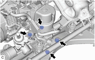
| (a) Remove the 3 nuts and separate the front engine mounting insulator from the front frame assembly. |
|
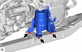
| (b) Remove the 4 nuts and separate the rear engine mounting insulator from the front frame assembly. |
|
5. REMOVE FRONT STABILIZER BAR WITH BRACKET Click here
6. REMOVE RACK AND PINION POWER STEERING GEAR ASSEMBLY
Click here 7. REMOVE FRONT LOWER NO. 1 SUSPENSION ARM SUB-ASSEMBLY LH
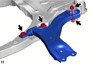
| (a) Remove the 3 bolts, nut and front lower No. 1 suspension arm sub-assembly LH from the front frame assembly.
NOTICE: Because the nut has its own stopper, do not turn the nut. Loosen the bolt with the nut secured. |
|
(b) Remove the front lower arm bushing stopper from the front lower No. 1 suspension arm sub-assembly.
8. REMOVE FRONT LOWER NO. 1 SUSPENSION ARM SUB-ASSEMBLY RH HINT:
Perform the same procedure as for the LH side. 9. REMOVE NO. 2 EXHAUST PIPE SUPPORT BRACKET
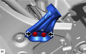
| (a) Remove the 2 bolts and No. 2 exhaust pipe support bracket from the front frame assembly. |
|
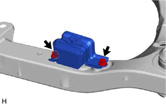
10. REMOVE FRONT SUSPENSION MEMBER DYNAMIC DAMPER
| (a) Remove the 2 bolts and front suspension member dynamic damper from the front frame assembly. |
|
11. REMOVE FRONT SUSPENSION MEMBER BODY MOUNTING FRONT STOPPER (a) Remove the 2 front suspension member body mounting front stoppers from the front frame assembly.
12. REMOVE FRONT SUSPENSION MEMBER BODY MOUNTING REAR STOPPER (a) Remove the 2 front suspension member body mounting rear stoppers from the front frame assembly.
13. REMOVE FRONT SUSPENSION MEMBER BODY MOUNTING FRONT CUSHION (for LH Side)
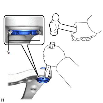
| (a)
Using a chisel and hammer, kink the flange of the front suspension
member body mounting front cushion as shown in the illustration. | |
(b) Apply lubricant to the contact surfaces of the front suspension member body mounting front cushion.
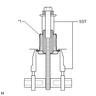
| (c) Install SST as shown in the illustration. SST: 09830-10010
09830-01010 09830-01040 09830-01050 SST: 09950-40011
09951-04020 09952-04010 09954-04010 09955-04011
09958-04011 NOTICE: Apply molybdenum grease to the threads and tip of the SST center bolt before use. |
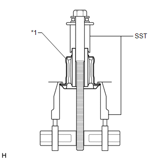
 |
|
*1 | Front Suspension Member Body Mounting Front Cushion | | |
(d)
Turn the SST center bolt as shown in the illustration to create a
clearance between the front suspension member body mounting front
cushion and the front frame assembly.
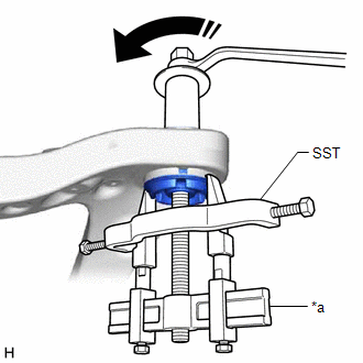
|
*a | Hold |
 |
Turn | (e)
While applying lubricant to the front suspension member body mounting
front cushion through the clearance, gradually remove the front
suspension member body mounting front cushion.
NOTICE:
- Tighten SST slowly and evenly.
- Be careful as the mounting cushion may fly out.
- The mounting cushion cannot be reused.
14. REMOVE FRONT SUSPENSION MEMBER BODY MOUNTING FRONT CUSHION (for RH Side)
HINT: Perform the same procedure as for the LH side. 15. REMOVE FRONT SUSPENSION MEMBER BODY MOUNTING REAR CUSHION LH
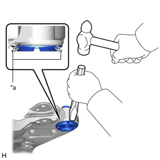
| (a)
Using a chisel and hammer, kink the flange of the front suspension
member body mounting rear cushion LH as shown in the illustration. |
|
(b) Apply lubricant to the contact surfaces of the front suspension member body mounting rear cushion LH.
| (c) Install SST as shown in the illustration. SST: 09830-10010
09830-01010 09830-01040 09830-01050 SST: 09950-40011
09951-04020 09952-04010 09954-04010 09955-04011
09958-04011 NOTICE: Apply molybdenum grease to the threads and tip of the SST center bolt before use. |
 |
|
*1 | Front Suspension Member Body Mounting Rear Cushion LH | | |
(d)
Turn the SST center bolt as shown in the illustration to create a
clearance between the front suspension member body mounting rear cushion
LH and the front frame assembly.
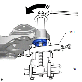
|
*a | Hold | |
|
Turn | (e)
While applying lubricant to the front suspension member body mounting
rear cushion LH through the clearance, gradually remove the front
suspension member body mounting rear cushion LH.
NOTICE:
- Tighten SST slowly and evenly.
- Be careful as the mounting cushion may fly out.
- The mounting cushion cannot be reused.
16. REMOVE FRONT SUSPENSION MEMBER BODY MOUNTING REAR CUSHION HINT:
Perform the same procedure as for the front suspension member body mounting rear cushion LH.
17. REMOVE HOLE PLUG (a) Remove the 7 hole plugs from the front frame assembly.
HINT: There are 2 different shapes of hole plug.
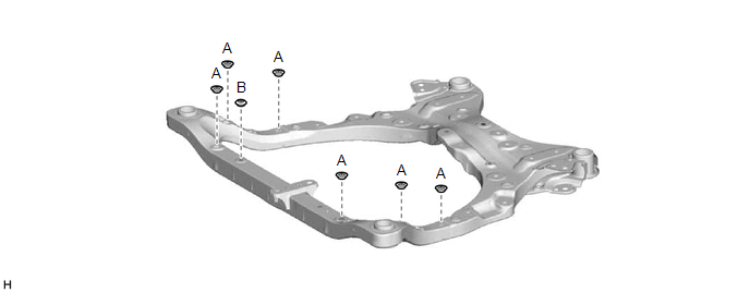 |