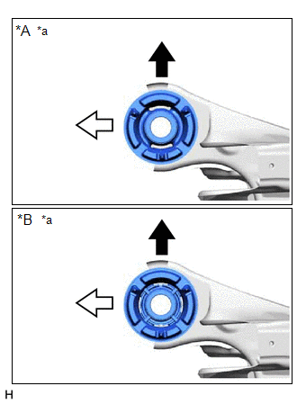
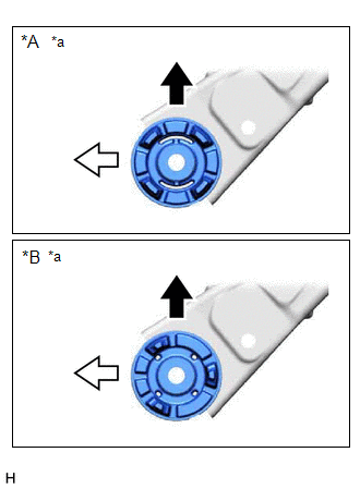
INSTALLATION PROCEDURE 1. INSTALL REAR SUSPENSION MEMBER FRONT BODY MOUNTING CUSHION (for LH Side) (a) Confirm the installation direction and temporarily install a new rear suspension member front body mounting cushion. NOTICE:
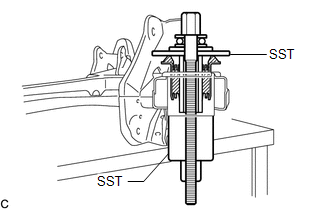
(c) Using SST, install the rear suspension member front body mounting cushion until there is no clearance between the rear suspension member sub-assembly and rear suspension member front body mounting cushion. SST: 09570-24011 SST: 09830-10010 09830-01010 09830-01020 09830-01040 09830-01050 NOTICE: If the rear suspension member sub-assembly is scratched, apply paint to the scratched areas of the rear suspension member sub-assembly. 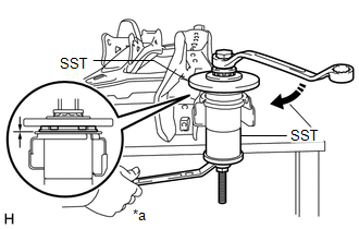
(d) Remove SST from the rear suspension member sub-assembly. 2. INSTALL REAR SUSPENSION MEMBER FRONT BODY MOUNTING CUSHION (for RH Side) (a) Confirm the installation direction and temporarily install a new rear suspension member front body mounting cushion. NOTICE:
(b) Install SST using the same procedure as for the rear suspension member front body mounting cushion (for LH Side). SST: 09570-24011 SST: 09830-10010 09830-01010 09830-01020 09830-01040 09830-01050 NOTICE: Apply molybdenum grease to the threads and tip of the SST center bolt before use. (c) Using SST, install the rear suspension member front body mounting cushion until there is no clearance between the rear suspension member sub-assembly and rear suspension member front body mounting cushion. SST: 09570-24011 SST: 09830-10010 09830-01010 09830-01020 09830-01040 09830-01050 NOTICE: If the rear suspension member sub-assembly is scratched, apply paint to the scratched areas of the rear suspension member sub-assembly. HINT: Perform the same procedure as for the rear suspension member front body mounting cushion (for LH Side). (d) Remove SST from the rear suspension member sub-assembly. 3. INSTALL REAR SUSPENSION MEMBER REAR BODY MOUNT CUSHION LH (a) Confirm the installation direction and temporarily install a new rear suspension member rear body mount cushion LH. NOTICE:
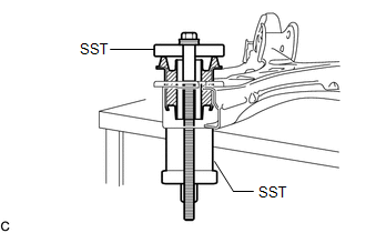
(c) Using SST, install the rear suspension member rear body mount cushion LH until there is no clearance between the rear suspension member sub-assembly and rear suspension member rear body mount cushion LH. SST: 09710-28031 09711-02030 09711-02040 94622-51200 SST: 09950-60021 09951-00720 09951-00890 NOTICE: If the rear suspension member sub-assembly is scratched, apply paint to the scratched areas of the rear suspension member sub-assembly. 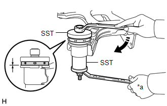
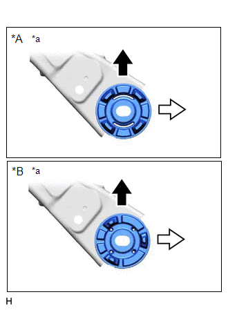
(d) Remove SST from the rear suspension member sub-assembly. 4. INSTALL REAR SUSPENSION MEMBER REAR BODY MOUNT CUSHION RH (a) Confirm the installation direction and temporarily install a new rear suspension member rear body mount cushion RH. NOTICE:
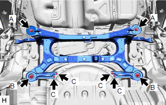
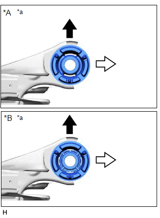
(b) Install SST using the same procedure as for the rear suspension member rear body mount cushion LH. SST: 09710-28031 09711-02030 09711-02040 94622-51200 SST: 09950-60021 09951-00720 09951-00890 NOTICE: Apply molybdenum grease to the threads and tip of the SST center bolt before use. (c) Using SST, install the rear suspension member rear body mount cushion RH until there is no clearance between the rear suspension member sub-assembly and rear suspension member rear body mount cushion RH. SST: 09710-28031 09711-02030 09711-02040 94622-51200 SST: 09950-60021 09951-00720 09951-00890 NOTICE: If the rear suspension member sub-assembly is scratched, apply paint to the scratched areas of the rear suspension member sub-assembly. HINT: Perform the same procedure as for the rear suspension member rear body mount cushion LH. (d) Remove SST from the rear suspension member sub-assembly. 5. INSTALL REAR UPPER CONTROL ARM ASSEMBLY LH Click here 6. INSTALL REAR UPPER CONTROL ARM ASSEMBLY RH HINT: Perform the same procedure as for the LH side. 7. INSTALL REAR SUSPENSION MEMBER SUB-ASSEMBLY (a) Install the 4 rear suspension member cushions to the rear suspension member sub-assembly. HINT: When reusing the rear suspension member cushion, make sure to check its identification mark and install it to the correct position. (b) Using an engine lifter and 4 attachments or equivalent tools, support the rear suspension member sub-assembly as shown in the illustration. 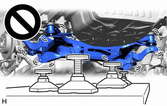
NOTICE:
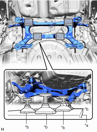
(c) Raise the rear suspension member sub-assembly until there is no clearance between the rear suspension member sub-assembly and vehicle.
8. TEMPORARILY INSTALL REAR UPPER CONTROL ARM ASSEMBLY LH (a) Temporarily install the rear upper control arm assembly LH to the rear axle carrier sub-assembly LH with the bolt and nut. NOTICE:
9. TEMPORARILY INSTALL REAR UPPER CONTROL ARM ASSEMBLY RH HINT: Perform the same procedure as for the LH side. 10. TEMPORARILY INSTALL REAR NO. 1 SUSPENSION ARM ASSEMBLY LH Click here 11. TEMPORARILY INSTALL REAR NO. 1 SUSPENSION ARM ASSEMBLY RH HINT: Perform the same procedure as for the LH side. 12. TEMPORARILY INSTALL REAR NO. 2 SUSPENSION ARM ASSEMBLY LH Click here 13. TEMPORARILY INSTALL REAR NO. 2 SUSPENSION ARM ASSEMBLY RH HINT: Perform the same procedure as for the LH side. 14. INSTALL REAR LOWER COIL SPRING INSULATOR LH Click here 15. INSTALL REAR LOWER COIL SPRING INSULATOR RH HINT: Perform the same procedure as for the LH side. 16. INSTALL REAR COIL SPRING LH Click here 17. INSTALL REAR COIL SPRING RH HINT: Perform the same procedure as for the LH side. 18. INSTALL REAR STABILIZER BAR Click here 19. CONNECT REAR FLEXIBLE HOSE LH (a) Connect the rear flexible hose LH to the rear flexible hose bracket with the bolt. Torque: 29 N·m {296 kgf·cm, 21 ft·lbf} 20. CONNECT REAR FLEXIBLE HOSE RH HINT: Perform the same procedure as for the LH side. 21. STABILIZE SUSPENSION Click here 22. INSTALL REAR STABILIZER LINK ASSEMBLY LH Click here 23. INSTALL REAR STABILIZER LINK ASSEMBLY RH HINT: Perform the same procedure as for the LH side. 24. INSTALL REAR NO. 1 SUSPENSION ARM ASSEMBLY LH Click here 25. INSTALL REAR NO. 1 SUSPENSION ARM ASSEMBLY RH HINT: Perform the same procedure as for the LH side. 26. INSTALL REAR NO. 2 SUSPENSION ARM ASSEMBLY LH (a) Install the rear No. 2 suspension arm assembly LH (rear axle carrier sub-assembly side) with the bolt. Click here 27. INSTALL REAR NO. 2 SUSPENSION ARM ASSEMBLY RH HINT: Perform the same procedure as for the LH side. 28. INSTALL REAR UPPER CONTROL ARM ASSEMBLY LH (a) Install the rear upper control arm assembly LH to the rear axle carrier sub-assembly LH with the bolt. Torque: 73 N·m {744 kgf·cm, 54 ft·lbf} NOTICE: Because the nut has its own stopper, do not turn the nut. Tighten the bolt with the nut secured. 29. INSTALL REAR UPPER CONTROL ARM ASSEMBLY RH HINT: Perform the same procedure as for the LH side. 30. INSTALL CENTER EXHAUST PIPE ASSEMBLY for 2GR-FKS: Click here
for A25A-FXS: Click here
31. INSTALL NO. 1 FLOOR UNDER COVER (for Gasoline Model) Click here 32. INSTALL NO. 2 FLOOR UNDER COVER (for Gasoline Model) Click here 33. INSTALL REAR WHEEL Click here 34. INSTALL REAR NO. 2 SUSPENSION ARM ASSEMBLY LH (a) Install the rear No. 2 suspension arm assembly LH (rear suspension member sub-assembly side) with the nut. Click here 35. INSTALL REAR NO. 2 SUSPENSION ARM ASSEMBLY RH HINT: Perform the same procedure as for the LH side. 36. INSPECT FOR EXHAUST GAS LEAK for 2GR-FKS: Click here for A25A-FXS: Click here
37. INSPECT AND ADJUST REAR WHEEL ALIGNMENT Click here 38. PERFORM INITIALIZATION for Gasoline Model:
|
Toyota Avalon (XX50) 2019-2022 Service & Repair Manual > Front Brake: Installation
INSTALLATION CAUTION / NOTICE / HINT NOTICE: Immediately after installing the brake pads, the braking performance may be reduced. Always perform a road test in a safe place while paying attention to the surroundings. After replacing the front disc brake pads, always perform a road test to check the ...