Toyota Avalon (XX50) 2019-2022 Service & Repair Manual: Removal

REMOVAL

CAUTION / NOTICE / HINT

The necessary procedures (adjustment, calibration, initialization, or registration) that must be performed after parts are removed and installed, or replaced during rear suspension member sub-assembly removal/installation are shown below.

Necessary Procedures After Parts Removed/Installed/Replaced (for Gasoline Model:)

Replaced Part or Performed Procedure

Necessary Procedure

Effect/Inoperative Function when Necessary Procedure not Performed

Link

Rear wheel alignment adjustment

Perform system variant learning and acceleration sensor zero point calibration.

  • VSC disabled or malfunctioning
  • DTCs are output
  • Slip indicator light illuminated
  • ABS warning light illuminated

Suspension, tires, etc.

(The vehicle height changes because of suspension or tire replacement.)

  • Measure ultrasonic sensor detection angle
  • Ultrasonic sensor detection angle registration
  • Intelligent Clearance Sonar System
  • Intuitive Parking Assist System

Rear television camera assembly optical axis adjustment (Back camera position setting)

Parking Assist Monitor System

for Initialization

for Calibration

  • Parking assist ECU initialization
  • Adjust steering angle
  • Television camera assembly optical axis adjustment (Back camera position setting)

Panoramic View Monitor System

for Initialization

for Calibration

Gas leak from exhaust system is repaired

Inspection After Repair

  • Poor idle, etc.
  • Engine start function, etc.

Necessary Procedures After Parts Removed/Installed/Replaced (for HV Model:)

Replaced Part or Performed Procedure

Necessary Procedure

Effect/Inoperative Function when Necessary Procedure not Performed

Link

Rear wheel alignment adjustment

  1. Clear zero point calibration data.
  2. Perform yaw rate and acceleration sensor zero point calibration.
  • DTCs are stored
  • ABS warning light illuminates
  • Brake warning light / yellow (minor malfunction) illuminates
  • Slip indicator light illuminates
  • VSC disabled or malfunctions

Suspension, tires, etc.

(The vehicle height changes because of suspension or tire replacement.)

  • Measure ultrasonic sensor detection angle
  • Ultrasonic sensor detection angle registration
  • Intelligent Clearance Sonar System
  • Intuitive Parking Assist System

Rear television camera assembly optical axis adjustment (Back camera position setting)

Parking Assist Monitor System

for Initialization

for Calibration

  • Parking assist ECU initialization
  • Adjust steering angle
  • Television camera assembly optical axis adjustment (Back camera position setting)

Panoramic View Monitor System

for Initialization

for Calibration

Gas leak from exhaust system is repaired

Inspection After Repair

  • Poor idle, etc.
  • Engine start function, etc.

CAUTION:

To prevent burns, do not touch the engine, exhaust pipe or other high temperature components while the engine is hot.

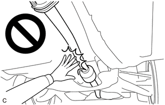
PROCEDURE

1. REMOVE REAR WHEEL

Click here

2. REMOVE NO. 2 FLOOR UNDER COVER (for Gasoline Model)

Click here

3. REMOVE NO. 1 FLOOR UNDER COVER (for Gasoline Model)

Click here

4. REMOVE CENTER EXHAUST PIPE ASSEMBLY

for 2GR-FKS: Click here

for A25A-FXS: Click here

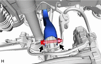
5. SEPARATE REAR FLEXIBLE HOSE LH

(a) Remove the bolt and separate the rear flexible hose LH from the rear flexible hose bracket.

6. SEPARATE REAR FLEXIBLE HOSE RH

HINT:

Perform the same procedure as for the LH side.

7. REMOVE REAR STABILIZER LINK ASSEMBLY LH

Click here

8. REMOVE REAR STABILIZER LINK ASSEMBLY RH

HINT:

Perform the same procedure as for the LH side.

9. REMOVE REAR STABILIZER BAR

Click here

10. REMOVE REAR COIL SPRING LH

Click here

11. REMOVE REAR COIL SPRING RH

HINT:

Perform the same procedure as for the LH side.

12. REMOVE REAR LOWER COIL SPRING INSULATOR LH

Click here

13. REMOVE REAR LOWER COIL SPRING INSULATOR RH

HINT:

Perform the same procedure as for the LH side.

14. REMOVE REAR NO. 2 SUSPENSION ARM ASSEMBLY LH

Click here

15. REMOVE REAR NO. 2 SUSPENSION ARM ASSEMBLY RH

HINT:

Perform the same procedure as for the LH side.

16. REMOVE REAR NO. 1 SUSPENSION ARM ASSEMBLY LH

Click here

17. REMOVE REAR NO. 1 SUSPENSION ARM ASSEMBLY RH

HINT:

Perform the same procedure as for the LH side.

18. SEPARATE REAR UPPER CONTROL ARM ASSEMBLY LH

(a) Remove the bolt and nut and separate the rear upper control arm assembly LH from the rear axle carrier sub-assembly LH.

NOTICE:

Because the nut has its own stopper, do not turn the nut. Loosen the bolt with the nut secured.

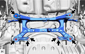
19. SEPARATE REAR UPPER CONTROL ARM ASSEMBLY RH

HINT:

Use the same procedure as for the LH side.

20. REMOVE REAR SUSPENSION MEMBER SUB-ASSEMBLY

(a) Using an engine lifter and 4 attachments or equivalent tools, support the rear suspension member sub-assembly as shown in the illustration.

  • The rear suspension member sub-assembly is a very heavy component. Make sure that it is supported securely.
  • If the rear suspension member sub-assembly is not securely supported, it may drop, resulting in serious injury.

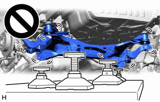
NOTICE:

Use attachments or equivalent tools to keep the rear suspension member sub-assembly level.

*a

Engine Lifter

*b

Attachment

Attachment Placement Location

(b) Remove the 2 bolts, 6 nuts, 2 rear suspension member lower stoppers, rear suspension member lower brace LH and rear suspension member lower brace RH.

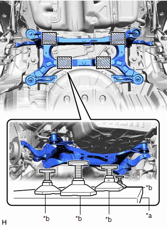
(c) Slowly lower the rear suspension member sub-assembly.

NOTICE:

When lowering the rear suspension member sub-assembly, be careful not to damage the vehicle body or other components installed to the vehicle.

(d) Remove the 4 rear suspension member cushions from the rear suspension member sub-assembly.

HINT:

Make sure to place an identification mark on the rear suspension member cushion so that they can be reinstalled to their original positions.

21. REMOVE REAR UPPER CONTROL ARM ASSEMBLY LH

Click here

22. REMOVE REAR UPPER CONTROL ARM ASSEMBLY RH

HINT:

Perform the same procedure as for the LH side.

23. REMOVE REAR SUSPENSION MEMBER FRONT BODY MOUNTING CUSHION (for LH Side)

(a) Using a chisel and hammer, bend the 2 portions of the rear suspension member front body mounting cushion rib.

NOTICE:

Make sure to bend the 2 portions of the cushion rib until the claws of SST can fit securely.

*a

Bend Portion

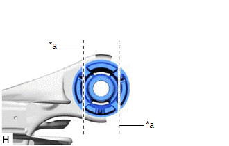
(b) Apply lubricant to the contact surfaces of the rear suspension member front body mounting cushion.

(c) Install SST as shown in the illustration.

SST: 09830-10010

09830-01010

09830-01040

09830-01050

SST: 09950-40011

09951-04010

09952-04010

09954-04010

09955-04061

09958-04011

NOTICE:

Apply molybdenum grease to the threads and tip of the SST center bolt before use.

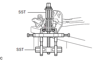
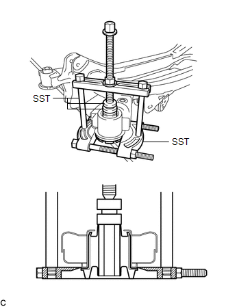
(d) Using SST, remove the rear suspension member front body mounting cushion while applying lubricant into the clearance between the rear suspension member front body mounting cushion and the rear suspension member sub-assembly.

SST: 09830-10010

09830-01010

09830-01040

09830-01050

SST: 09950-40011

09951-04010

09952-04010

09954-04010

09955-04061

09958-04011

NOTICE:

  • Set the claws of SST into the rear suspension member sub-assembly securely as shown in the illustration.
  • Tighten SST slowly and evenly.
  • Be careful as the rear suspension member front body mounting cushion may fly out.
  • The rear suspension member front body mounting cushion cannot be reused.

*a

Hold

Turn

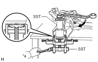
(e) Remove SST and the rear suspension member front body mounting cushion from the rear suspension member sub-assembly.

24. REMOVE REAR SUSPENSION MEMBER FRONT BODY MOUNTING CUSHION (for RH Side)

HINT:

Perform the same procedure as for the LH side.

25. REMOVE REAR SUSPENSION MEMBER REAR BODY MOUNT CUSHION LH

(a) Install SST as shown in the illustration.

SST: 09950-00020

SST: 09950-00030

SST: 09950-60011

09951-00330

NOTICE:

Apply molybdenum grease to the threads and tip of the SST center bolt before use.

(b) Using SST, remove the rear suspension member rear body mount cushion LH while applying lubricant into the clearance between the rear suspension member rear body mount cushion LH and the rear suspension member sub-assembly.

SST: 09950-00020

SST: 09950-00030

SST: 09950-60011

09951-00330

NOTICE:

  • Tighten SST slowly and evenly.
  • Be careful as the rear suspension member rear body mount cushion LH may fly out.
  • The rear suspension member rear body mount cushion LH cannot be reused.

*a

Hold

Turn

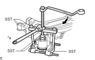
(c) Remove SST and the rear suspension member rear body mount cushion LH from the rear suspension member sub-assembly.

26. REMOVE REAR SUSPENSION MEMBER REAR BODY MOUNT CUSHION RH

HINT:

Perform the same procedure as for the LH side.

    Installation

    Rear Suspension System

    See More:

    Toyota Avalon (XX50) 2019-2022 Service & Repair Manual > Motor Cable: Removal
    REMOVAL CAUTION / NOTICE / HINT The necessary procedures (adjustment, calibration, initialization, or registration) that must be performed after parts are removed and installed, or replaced during motor cable removal/installation are shown below. Necessary Procedures After Parts Removed/Installed/Re ...

    Toyota Avalon (XX50) 2019-2022 Owners Manual

    Toyota Avalon (XX50) 2019-2022 Service & Repair Manual

    © 2024 Copyright www.tavalon.net
    0.0174