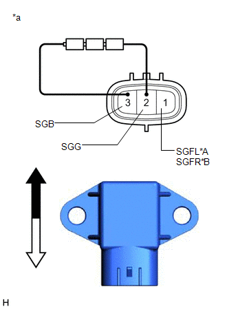
INSPECTION PROCEDURE 1. INSPECT ACCELERATION SENSOR ASSEMBLY (a) Connect 3 1.5 V dry cell batteries in series. (b) Connect a positive (+) lead from the batteries to terminal 3 (SGB) and a negative (-) lead to terminal 2 (SGG). (c) Measure the voltage according to the value(s) in the table below. Standard Voltage: for LH Side
NOTICE:
HINT: When the front acceleration sensor assembly is tilted, it may output a different value. If the result is not as specified, replace the front acceleration sensor assembly. |
Toyota Avalon (XX50) 2019-2022 Service & Repair Manual > Audio And Visual System(for Hv Model): Vehicle Speed Signal Circuit between Stereo Component Amplifier and Combination Meter
DESCRIPTION The stereo component amplifier assembly receives a vehicle speed signal from the combination meter assembly to control the ASL function. HINT: A voltage of 12 V or 5 V is output from each ECU and then input to the combination meter assembly. The signal is changed to a pulse signal at the ...


