INSTALLATION CAUTION / NOTICE / HINT HINT:
PROCEDURE 1. PRECAUTION NOTICE: After turning the engine switch (for Gasoline Model) or power switch (for HV Model) off, waiting time may be required before disconnecting the cable from the negative (-) auxiliary battery terminal. Therefore, make sure to read the disconnecting the cable from the negative (-) auxiliary battery terminal notices before proceeding with work. Click here
2. REPAIR INSTRUCTION Click here
3. INSTALL NO. 2 BLACK OUT TAPE (a) Refer to the illustration to position a new No. 2 black out tape. 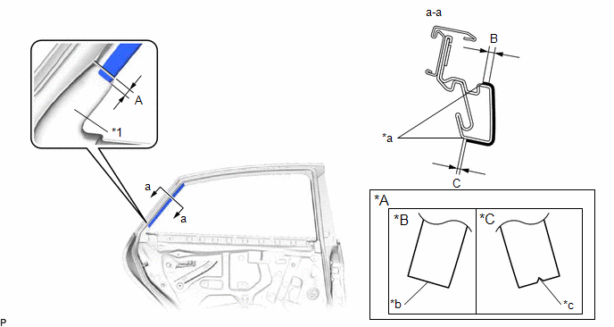
Standard Measurement:
(b) Remove the release paper and apply the No. 2 black out tape. 4. INSTALL NO. 3 BLACK OUT TAPE (a) Refer to the illustration to position a new No. 3 black out tape. 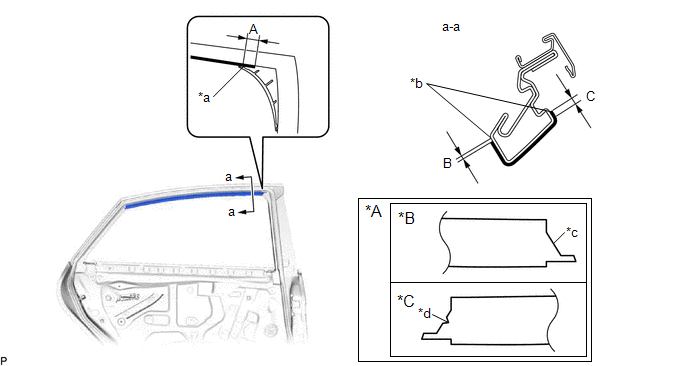
Standard Measurement:
(b) Remove the release paper and apply the No. 3 black out tape. 5. INSTALL NO. 1 BLACK OUT TAPE (a) Refer to the illustration to position a new No. 1 black out tape. 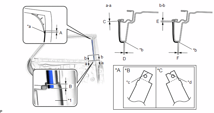
Standard Measurement:
(b) Remove the release paper and apply the No. 1 black out tape. 6. INSTALL REAR DOOR FRAME GARNISH Click here 7. INSTALL REAR DOOR WEATHERSTRIP Click here 8. INSTALL REAR DOOR CHECK ASSEMBLY Click here 9. INSTALL REAR DOOR GLASS SUB-ASSEMBLY Click here 10. INSTALL REAR DOOR REAR GUIDE SEAL Click here 11. CONNECT REAR DOOR WEATHERSTRIP Click here 12. INSTALL REAR DOOR REAR LOWER WINDOW FRAME SUB-ASSEMBLY Click here 13. INSTALL REAR DOOR GLASS RUN Click here 14. INSTALL REAR DOOR NO. 2 SERVICE HOLE COVER Click here 15. INSTALL REAR DOOR INNER GLASS WEATHERSTRIP Click here 16. INSTALL REAR DOOR SERVICE HOLE COVER Click here 17. INSTALL REAR DOOR NO. 1 TRIM BRACKET Click here 18. INSTALL REAR DOOR TRIM BOARD SUB-ASSEMBLY Click here 19. INSTALL REAR POWER WINDOW REGULATOR SWITCH ASSEMBLY WITH REAR DOOR UPPER ARMREST BASE PANEL Click here 20. INSTALL REAR DOOR TRIM ASSEMBLY COVER Click here 21. INSTALL REAR DOOR ARMREST COVER SUB-ASSEMBLY Click here 22. CONNECT CABLE TO NEGATIVE AUXILIARY BATTERY TERMINAL for A25A-FXS: Click here for 2GR-FKS: Click here 23. INSTALL LUGGAGE TRIM SERVICE HOLE COVER (for HV Model) Click here 24. INITIALIZE POWER WINDOW CONTROL SYSTEM for Gasoline Model: Click here for HV Model: Click here 25. INSPECT POWER WINDOW OPERATION for Gasoline Model: Click here for HV Model: Click here |
Toyota Avalon (XX50) 2019-2022 Service & Repair Manual > Lighting System(for Hv Model With Cornering Light): Steering Position Sensor (B2414)
DESCRIPTION The headlight ECU sub-assembly LH receives steering angle signals from the steering sensor via CAN communication and performs light control. DTC No. Detection Item DTC Detection Condition Trouble Area DTC Output from B2414 Steering Position Sensor The power switch is on (IG). Sensor malf ...


