DESCRIPTION This circuit is from the parking brake ECU (brake actuator assembly) to the radio and display receiver assembly. WIRING DIAGRAM 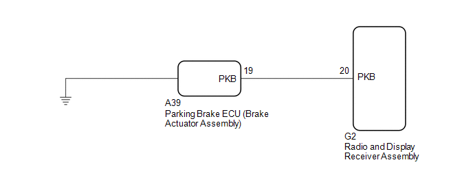 PROCEDURE
(a) Check that the brake warning light comes on when the parking brake is applied and goes off when it is released. OK: The brake warning light operates as specified above.
(a) Disconnect the G2 radio and display receiver assembly connector. (b) Disconnect the A39 parking brake ECU (brake actuator assembly) connector. (c) Measure the resistance according to the value(s) in the table below. Standard Resistance:
|
Toyota Avalon (XX50) 2019-2022 Service & Repair Manual > Power Tilt And Power Telescopic Steering Column System(for Hv Model): Fail-safe Chart
FAIL-SAFE CHART HINT: If the power source voltage to the multiplex tilt and telescopic ECU returns to normal within 10 seconds during tilt or telescopic operation, the operation will be resumed. If it returns to normal after 10 seconds have elapsed, the operation restarts when a tilt or telescopic o ...


