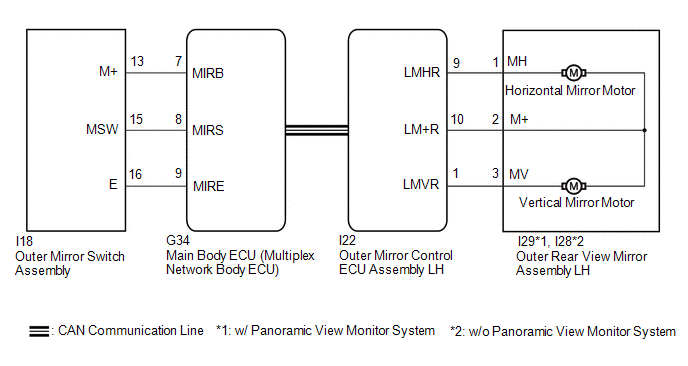
DESCRIPTION The outer
mirror switch assembly sends the mirror adjust switch signals to the
main body ECU (multiplex network body ECU). The main body ECU (multiplex
network body ECU) then sends the received mirror adjust switch signals
to the outer mirror control ECU assembly LH via CAN communication. On
receiving the signal, the outer mirror control ECU assembly LH operates
the vertical and horizontal mirror motors, which are built into the
outer rear view mirror assembly LH, to adjust the mirror surface
position. WIRING DIAGRAM
 CAUTION / NOTICE / HINT
NOTICE:
- The power mirror control system (for Gasoline Model with Memory) uses
the CAN communication system. Inspect the communication functions by
following How to Proceed with Troubleshooting. Troubleshoot the power
mirror control system (for Gasoline Model with Memory) after confirming
that the communication systems are functioning properly.
Click here 
- Before replacing the main body ECU (multiplex network body ECU), refer to Registration.
Click here
PROCEDURE |
1. | READ VALUE USING TECHSTREAM |
(a) Connect the Techstream to the DLC3. (b) Turn the engine switch on (IG).
(c) Turn the Techstream on. (d) Enter the following menus: Body Electrical / Main Body / Data List.
(e) Read the Data List according to the display on the Techstream. Body Electrical > Main Body > Data List
|
Tester Display | Measurement Item |
Range | Normal Condition |
Diagnostic Note | |
Mirror Selection SW (R) |
Mirror select switch signal for RH mirror |
OFF or ON | OFF: Mirror select switch off
ON: Mirror select switch R switch on |
- | | Mirror Selection SW (L) |
Mirror select switch signal for LH mirror |
OFF or ON | OFF: Mirror select switch off
ON: Mirror select switch L switch on |
- | | Mirror Position SW (R) |
Mirror adjust switch signal (Right) |
OFF or ON | OFF: Mirror adjust switch not pushed right
ON: Mirror adjust switch pushed right |
Check with the mirror select switch L or R selected | |
Mirror Position SW (L) |
Mirror adjust switch signal (Left) |
OFF or ON | OFF: Mirror adjust switch not pushed left
ON: Mirror adjust switch pushed left |
Check with the mirror select switch L or R selected | |
Mirror Position SW (Up) |
Mirror adjust switch signal (Up) |
OFF or ON | OFF: Mirror adjust switch not pushed up
ON: Mirror adjust switch pushed up |
Check with the mirror select switch L or R selected | |
Mirror Position SW (Dwn) |
Mirror adjust switch signal (Down) |
OFF or ON | OFF: Mirror adjust switch not pushed down
ON: Mirror adjust switch pushed down |
Check with the mirror select switch L or R selected | Body Electrical > Main Body > Data List
|
Tester Display | | Mirror Selection SW (R) | |
Mirror Selection SW (L) | |
Mirror Position SW (R) | |
Mirror Position SW (L) | |
Mirror Position SW (Up) | |
Mirror Position SW (Dwn) | OK:
On the Techstream screen, ON or OFF is displayed accordingly.
| NG |
 | GO TO STEP 4 |
|
OK |
 | |
| 2. |
INSPECT OUTER REAR VIEW MIRROR ASSEMBLY LH (MIRROR SURFACE) |
(a) Remove the outer rear view mirror assembly LH. Click here
(b) Inspect the outer rear view mirror assembly LH (mirror surface).
Click here
| NG |
| REPLACE OUTER REAR VIEW MIRROR ASSEMBLY LH |
|
OK | |
| |
| 3. |
CHECK HARNESS AND CONNECTOR (OUTER REAR VIEW MIRROR ASSEMBLY LH - OUTER MIRROR CONTROL ECU ASSEMBLY LH) |
(a) Disconnect the I29*1 or I28*2 outer rear view mirror assembly LH.
- *1: w/ Panoramic View Monitor System
- *2: w/o Panoramic View Monitor System
(b) Disconnect the I22 outer mirror control ECU assembly LH. (c) Measure the resistance according to the value(s) in the table below.
Standard Resistance: w/ Panoramic View Monitor System |
Tester Connection | Condition |
Specified Condition | |
I29-3 (MV) - I22-1 (LMVR) |
Always | Below 1 Ω | |
I29-1 (MH) - I22-9 (LMHR) |
Always | Below 1 Ω | |
I29-2 (M+) - I22-10 (LM+R) |
Always | Below 1 Ω | |
I29-3 (MV) or I22-1 (LMVR) - Body ground |
Always | 10 kΩ or higher | |
I29-1 (MH) or I22-9 (LMHR) - Body ground |
Always | 10 kΩ or higher | |
I29-2 (M+) or I22-10 (LM+R) - Body ground |
Always | 10 kΩ or higher | w/o Panoramic View Monitor System |
Tester Connection | Condition |
Specified Condition | |
I28-3 (MV) - I22-1 (LMVR) |
Always | Below 1 Ω | |
I28-1 (MH) - I22-9 (LMHR) |
Always | Below 1 Ω | |
I28-2 (M+) - I22-10 (LM+R) |
Always | Below 1 Ω | |
I28-3 (MV) or I22-1 (LMVR) - Body ground |
Always | 10 kΩ or higher | |
I28-1 (MH) or I22-9 (LMHR) - Body ground |
Always | 10 kΩ or higher | |
I28-2 (M+) or I22-10 (LM+R) - Body ground |
Always | 10 kΩ or higher |
| OK |
| REPLACE OUTER MIRROR CONTROL ECU ASSEMBLY LH |
| NG |
| REPAIR OR REPLACE HARNESS OR CONNECTOR |
| 4. |
INSPECT OUTER MIRROR SWITCH ASSEMBLY | (a) Remove the outer mirror switch assembly.
Click here (b) Inspect the outer mirror switch assembly.
Click here
| NG |
| REPLACE OUTER MIRROR SWITCH ASSEMBLY |
|
OK | |
| |
| 5. |
CHECK HARNESS AND CONNECTOR (OUTER MIRROR SWITCH ASSEMBLY - MAIN BODY ECU (MULTIPLEX NETWORK BODY ECU)) |
(a) Disconnect the I18 outer mirror switch assembly. (b) Disconnect the G34 main body ECU (multiplex network body ECU).
(c) Measure the resistance according to the value(s) in the table below.
Standard Resistance: |
Tester Connection | Condition |
Specified Condition | |
I18-16 (E) - G34-9 (MIRE) |
Always | Below 1 Ω | |
I18-13 (M+) - G34-7 (MIRB) |
Always | Below 1 Ω | |
I18-15 (MSW) - G34-8 (MIRS) |
Always | Below 1 Ω | |
I18-16 (E) or G34-9 (MIRE) - Body ground |
Always | 10 kΩ or higher | |
I18-13 (M+) or G34-7 (MIRB) - Body ground |
Always | 10 kΩ or higher | |
I18-15 (MSW) or G34-8 (MIRS) - Body ground |
Always | 10 kΩ or higher |
| OK |
| REPLACE MAIN BODY ECU (MULTIPLEX NETWORK BODY ECU) |
| NG |
| REPAIR OR REPLACE HARNESS OR CONNECTOR | | 

