DESCRIPTION If any of the M1 or M2 seat memory switch is pressed, the outer mirror control ECU assembly LH detects the switch operation and sends the seat memory switch signal to the main body ECU (multiplex network body ECU) via CAN communication. The main body ECU (multiplex network body ECU) sends the reproduction signal to each outer mirror control ECU assembly via CAN communication. When receiving the reproduction signal, each outer mirror control ECU assembly operates the vertical and horizontal mirror motors, which are built into the outer rear view mirror assembly, to adjust the mirror surface to the stored position. WIRING DIAGRAM 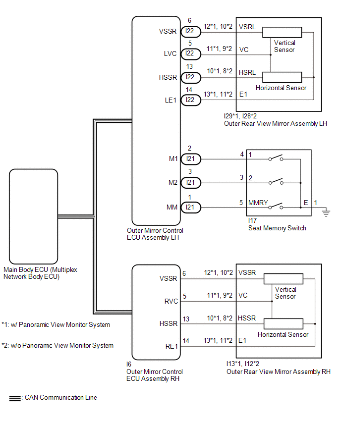 CAUTION / NOTICE / HINT NOTICE:
PROCEDURE
(a) When any seat memory switch (M1 or M2) is pressed, check that the driver seat moves to the memorized position. Click here OK: Driver seat moves to the memorized position.
(a) Check the electrical remote control mirror function. Click here
OK: Electrical remote control mirror function is normal.
(a) Connect the Techstream to the DLC3. (b) Turn the engine switch on (IG). (c) Turn the Techstream on. (d) Enter the following menus: Body Electrical / Mirror L or Mirror R / Data List. (e) Read the Data List according to the display on the Techstream. Body Electrical > Mirror L > Data List
OK: ON (Memorized) appears on the screen.
(b) Using the outer mirror switch assembly, turn the mirror surface to the fully left position. (c) Press the M1 switch while the SET switch is being pressed. (d) Check that the buzzer sounds for 0.5 seconds and the mirror surface position is memorized. (e) Using the outer mirror switch assembly, turn the mirror surface to the fully right position. (f) Press the M1 switch. (g) Check that the buzzer sounds for 0.1 seconds and the outer mirror automatically moves to the memorized fully left position.
(a) Temporarily replace the outer rear view mirror assembly LH with a new or known good one. Click here
(b) Using the outer mirror switch assembly, turn the mirror surface to the fully left position. (c) Press the M1 switch while the SET switch is being pressed. (d) Check that the buzzer sounds for 0.5 seconds and the mirror surface position is memorized. (e) Using the outer mirror switch assembly, turn the mirror surface to the fully right position. (f) Press the M1 switch. (g) Check that the buzzer sounds for 0.1 seconds and the outer mirror automatically moves to the memorized fully left position.
(a) Temporarily replace the outer rear view mirror assembly RH with a new or known good one. Click here
(b) Using the outer mirror switch assembly, turn the mirror surface to the fully left position. (c) Press the M1 switch while the SET switch is being pressed. (d) Check that the buzzer sounds for 0.5 seconds and the mirror surface position is memorized. (e) Using the outer mirror switch assembly, turn the mirror surface to the fully right position. (f) Press the M1 switch. (g) Check that the buzzer sounds for 0.1 seconds and the outer mirror automatically moves to the memorized fully left position.
|
Toyota Avalon (XX50) 2019-2022 Service & Repair Manual > Safety Connect System(for Hv Model): Manual Button Malfunction (B15C5)
DESCRIPTION This DTC is set when the DCM (Telematics Transceiver) detects an open or short circuit in the manual (SOS) switch. DTC No. Detection Item DTC Detection Condition Trouble Area B15C5 Manual Button Malfunction Open or short circuit in manual (SOS) switch is detected. DCM (Telematics Transce ...