Toyota Avalon (XX50) 2019-2022 Service & Repair Manual: All Doors LOCK/UNLOCK Functions do not Operate Via Door Control Switch

DESCRIPTION

The main body ECU (multiplex network body ECU) receives switch signals from the door control switch assembly and activates the door lock motor on each door according to these signals.

WIRING DIAGRAM

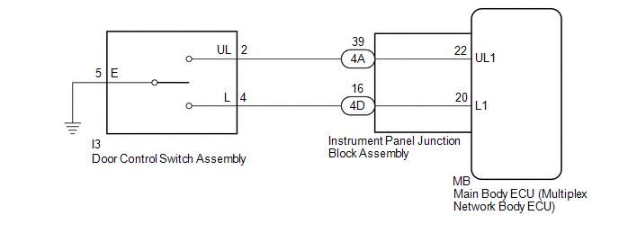
CAUTION / NOTICE / HINT

NOTICE:

Before replacing the main body ECU (multiplex network body ECU), refer to Registration.

Click here

PROCEDURE

1.

READ VALUE USING TECHSTREAM (Door Lock SW-Lock, Door Lock SW-Unlock)

(a) Connect the Techstream to the DLC3.

(b) Turn the engine switch on (IG).

(c) Turn the Techstream on.

(d) Enter the following menus: Body Electrical / Main Body / Data List.

(e) Read the Data List according to the display on the Techstream.

Body Electrical > Main Body > Data List

Tester Display

Measurement Item

Range

Normal Condition

Diagnostic Note

Door Lock SW-Lock

Door control switch assembly lock signal

OFF or ON

OFF: Lock side of door control switch assembly not pushed

ON: Lock side of door control switch assembly pushed

-

Door Lock SW-Unlock

Door control switch assembly unlock signal

OFF or ON

OFF: Unlock side of door control switch assembly not pushed

ON: Unlock side of door control switch assembly pushed

-

Body Electrical > Main Body > Data List

Tester Display

Door Lock SW-Lock

Door Lock SW-Unlock

OK:

The Techstream indicates ON or OFF according to the switch operation shown in the table.

OK

REPLACE MAIN BODY ECU (MULTIPLEX NETWORK BODY ECU)

NG

2.

INSPECT DOOR CONTROL SWITCH ASSEMBLY

(a) Remove the door control switch assembly.

Click here

(b) Inspect the door control switch assembly.

Click here

NG

REPLACE DOOR CONTROL SWITCH ASSEMBLY

OK

3.

CHECK HARNESS AND CONNECTOR (DOOR CONTROL SWITCH ASSEMBLY - INSTRUMENT PANEL JUNCTION BLOCK ASSEMBLY AND BODY GROUND)

(a) Disconnect the 4A and 4D instrument panel junction block assembly connectors.

(b) Measure the resistance according to the value(s) in the table below.

Standard Resistance:

Tester Connection

Condition

Specified Condition

I3-2 (UL) - 4A-39

Always

Below 1 Ω

I3-4 (L) - 4D-16

Always

Below 1 Ω

I3-5 (E) - Body ground

Always

Below 1 Ω

4A-39 or I3-2 (UL) - Body ground

Always

10 kΩ or higher

4D-16 or I3-4 (L) - Body ground

Always

10 kΩ or higher

NG

REPAIR OR REPLACE HARNESS OR CONNECTOR

OK

4.

INSPECT INSTRUMENT PANEL JUNCTION BLOCK ASSEMBLY

(a) Remove the instrument panel junction block assembly.

Click here

(b) Remove the main body ECU (multiplex network body ECU).

*a

Component without harness connected

(Instrument Panel Junction Block Assembly)

-

-

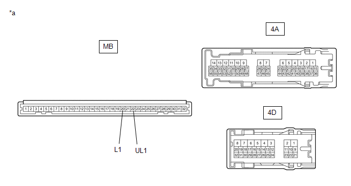
(c) Measure the resistance according to the value(s) in the table below.

Standard Resistance:

Tester Connection

Condition

Specified Condition

MB-22 (UL1) - 4A-39

Always

Below 1 Ω

MB-20 (L1) - 4D-16

Always

Below 1 Ω

OK

REPLACE MAIN BODY ECU (MULTIPLEX NETWORK BODY ECU)

NG

REPLACE INSTRUMENT PANEL JUNCTION BLOCK ASSEMBLY

    Power Door Lock Control System(for Gasoline Model)

    All Doors LOCK/UNLOCK Functions do not Operate Via Door Key Cylinder

    See More:

    Toyota Avalon (XX50) 2019-2022 Service & Repair Manual > Mass Air Flow Meter: Removal
    REMOVAL CAUTION / NOTICE / HINT The necessary procedures (adjustment, calibration, initialization, or registration) that must be performed after parts are removed and installed, or replaced during mass air flow meter sub-assembly removal/installation are shown below. Necessary Procedures After Parts ...

    Toyota Avalon (XX50) 2019-2022 Owners Manual

    Toyota Avalon (XX50) 2019-2022 Service & Repair Manual

    © 2024 Copyright www.tavalon.net
    0.0111