DESCRIPTION The thermistor assembly is installed in front of the cooler condenser assembly to detect the ambient temperature, which is used to control the automatic air conditioning system. The thermistor assembly detects fluctuations in the ambient temperature and sends it as a signal to the combination meter assembly. This data is used for controlling the cabin temperature. The resistance of the thermistor assembly changes in accordance with the ambient temperature. As the temperature decreases, the resistance increases. As the temperature increases, the resistance decreases. The combination meter assembly applies voltage (5 V) to the thermistor assembly and detects voltage changes due to changes in the resistance of the thermistor assembly. NOTICE: The thermistor assembly detects the ambient temperature in its vicinity, not the ambient temperature around the vehicle. Depending on factors such as radiant heat from the engine room and the vehicle speed, the ambient temperature detected by the thermistor assembly may differ from the ambient temperature displayed on the multi-information display in the combination meter assembly. For example:
WIRING DIAGRAM 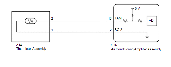 CAUTION / NOTICE / HINT NOTICE:
PROCEDURE
(a) Check for DTCs. Body Electrical > Air Conditioner > Trouble Codes
(a) Remove the thermistor assembly. Click here (b) Inspect the thermistor assembly. Click here
(a) Disconnect the G36 air conditioning amplifier assembly connector. (b) Measure the resistance according to the value(s) in the table below. Standard Resistance:
(a) Disconnect the cable from the negative (-) battery terminal and wait for at least 90 seconds. NOTICE: After turning the engine switch off, waiting time may be required before disconnecting the cable from the negative (-) battery terminal. Therefore, make sure to read the disconnecting the cable from the negative (-) battery terminal notices before proceeding with work. Click here
HINT: The air conditioning amplifier assembly stores the value of the last ambient temperature detected by the thermistor assembly before the engine switch was turned off for up to 1 hour after the engine switch is turned off. It is necessary to clear this value. (b) Connect the cable to the negative (-) battery terminal. (c) Measure and make a note of the ambient temperature near the thermistor assembly using a thermometer. NOTICE:
(d) Make a note of the ambient temperature displayed on the multi-information display in the combination meter assembly. (e) Compare the value of the ambient temperature measured by the thermometer and the thermistor assembly. OK: The value of the ambient temperature measured by the thermometer and the thermistor assembly are almost the same.
|
Toyota Avalon (XX50) 2019-2022 Service & Repair Manual > Lane Departure Alert System (w/ Steering Control)(for Hv Model): How To Proceed With Troubleshooting
CAUTION / NOTICE / HINT HINT: Use these procedures to troubleshoot the lane departure alert system (w/ steering control). *: Use the Techstream. PROCEDURE 1. VEHICLE BROUGHT TO WORKSHOP NEXT 2. INSPECT AUXILIARY BATTERY VOLTAGE (a) Measure the auxiliary battery voltage with the power switch off. Sta ...


