DESCRIPTION The air conditioning control panel (radio and display receiver assembly) communicates with the air conditioning amplifier assembly via LIN communication. If a malfunction occurs in the LIN communication system, the air conditioning amplifier assembly will not operate, even if the air conditioning control panel (radio and display receiver assembly) is operated.
WIRING DIAGRAM 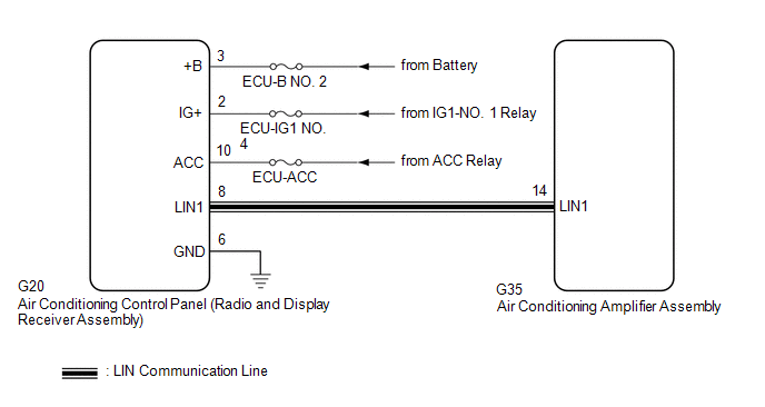 CAUTION / NOTICE / HINT NOTICE: Inspect the fuses for circuits related to this system before performing the following procedure. PROCEDURE
(a) Disconnect the G20 air conditioning control panel (radio and display receiver assembly) connector. (b) Measure the voltage and resistance according to the value(s) in the table below. Standard Voltage:
Standard Resistance:
(a) Disconnect the G35 air conditioning amplifier assembly connector. (b) Measure the resistance according to the value(s) in the table below. Standard Resistance:
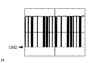 (a) Connect the G35 air conditioning amplifier assembly connector. (b) Turn the engine switch on (IG). (c) Using an oscilloscope, check the waveform.
OK: Waveform is similar to that shown in the illustration.
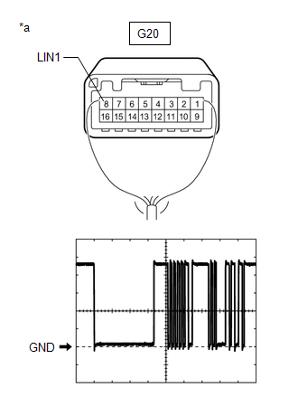
(a) Connect the G20 air conditioning control panel (radio and display receiver assembly) connector. (b) Turn the engine switch on (IG). (c) Using an oscilloscope, check the waveform.
OK: Waveform is similar to that shown in the illustration.
|
Toyota Avalon (XX50) 2019-2022 Service & Repair Manual > Sliding Roof System(for Hv Model): Terminals Of Ecu
TERMINALS OF ECU CHECK SLIDING ROOF ECU (SLIDING ROOF DRIVE GEAR ASSEMBLY) (a) Disconnect the O3 sliding roof ECU (sliding roof drive gear assembly) connector. (b) Measure the resistance and voltage according to the value(s) in the table below. HINT: Measure the values on the wire harness side with ...


