DESCRIPTION The cooler (room temp. sensor) thermistor is installed in the instrument panel to detect the cabin temperature, which is used to control the air conditioning system. The resistance of the cooler (room temp. sensor) thermistor changes in accordance with the cabin temperature. As the temperature decreases, the resistance increases. As the temperature increases, the resistance decreases. The air conditioning amplifier assembly applies voltage (5 V) to the cooler (room temp. sensor) thermistor and reads voltage changes due to changes in the resistance of the cooler (room temp. sensor) thermistor.
HINT: If the cabin temperature is approximately -18.6°C (-1.48°F) or lower, DTC B1411 may be stored even though the system is normal. WIRING DIAGRAM 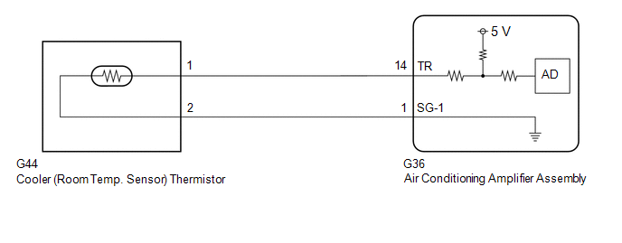 PROCEDURE
(a) Connect the Techstream to the DLC3. (b) Turn the engine switch on (IG). (c) Turn the Techstream on. (d) Enter the following menus: Body Electrical / Air Conditioner / Data List. (e) Read the Data List according to the display on the Techstream. Body Electrical > Air Conditioner > Data List
OK: The display is as specified in the normal condition column.
(a) Remove the cooler (room temp. sensor) thermistor. Click here
(b) Inspect the cooler (room temp. sensor) thermistor. Click here
(a) Disconnect the G36 air conditioning amplifier assembly connector. (b) Measure the resistance according to the value(s) in the table below. Standard Resistance:
|
Toyota Avalon (XX50) 2019-2022 Service & Repair Manual > Cooling Fan System: Cooling Fan Circuit
DESCRIPTION The ECM calculates an appropriate cooling fan speed based on the engine coolant temperature, air conditioning switch status, refrigerant pressure, engine speed and vehicle speed, and sends a signal to the cooling fan ECU (fan with motor assembly). The cooling fan ECU (fan with motor asse ...


