DESCRIPTION The No. 1 cooler thermistor is installed to the evaporator in the air conditioner unit to detect the temperature of the cooled air that has passed through the evaporator, which is used to control the air conditioning system. It sends signals to the air conditioning amplifier assembly. The resistance of the No. 1 cooler thermistor changes in accordance with the temperature of the cooled air that has passed through the evaporator. As the temperature decreases, the resistance increases. As the temperature increases, the resistance decreases. The air conditioning amplifier assembly applies voltage (5 V) to the No. 1 cooler thermistor and reads voltage changes as the resistance of the No. 1 cooler thermistor changes. This sensor is used for frost prevention.
WIRING DIAGRAM 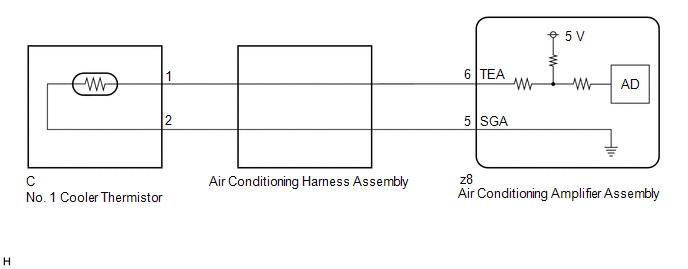 PROCEDURE
(a) Connect the Techstream to the DLC3. (b) Turn the engine switch on (IG) (c) Turn the Techstream on. (d) Enter the following menus: Body Electrical / Air Conditioner / Data List. (e) Read the Data List according to the display on the Techstream. Body Electrical > Air Conditioner > Data List
OK: The display is as specified in the normal condition column.
(a) Remove the No. 1 cooler thermistor. Click here (b) Inspect the No. 1 cooler thermistor. Click here
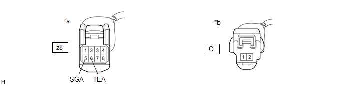
(a) Remove the air conditioning harness assembly. Click here (b) Measure the resistance according to the value(s) in the table below. Standard Resistance:
|
Toyota Avalon (XX50) 2019-2022 Service & Repair Manual > Can Communication System(for Hv Model): ECU Malfunction (B1003)
DESCRIPTION DTC No. Detection Item DTC Detection Condition Trouble Area Note B1003 ECU Malfunction A malfunction in the non-volatile storage of the central gateway ECU (network gateway ECU) is detected. Central gateway ECU (network gateway ECU) - PROCEDURE 1. RECONFIRM DTC OUTPUT (a) Connect the Tec ...


