|
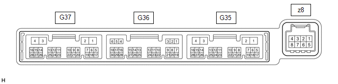
Terminal No. (Symbol) |
Wiring Color | Terminal Description |
Condition | Specified Condition |
|
G36-1 (SG-1) - Body ground |
LG - Body ground | Ground for cooler (room temp. sensor) thermistor |
Always | Below 1 V |
|
G36-2 (SG-2) - Body ground |
W - Body ground | Ground for thermistor assembly |
Always | Below 1 V |
|
G36-3 (SG-4) - Body ground |
L - Body ground | Ground for air conditioner pressure sensor |
Always | Below 1 V |
|
G36-6 (S5-3) - G36-3 (SG-4) |
GR - L | Power supply for air conditioner pressure sensor |
Engine switch on (IG) |
4.75 to 5.25 V |
| Engine switch off |
Below 1 V |
|
G36-9 (MGC) - G35-4 (GND) |
G - W-B | Magnetic clutch operation signal |
- Engine running
- Blower switch: LO
- A/C switch: Off
| 11 to 14 V |
- Engine running
- Blower switch: LO
- A/C switch: On
| Below 1 V |
|
G36-13 (TAM) - G36-2 (SG-2) |
R - W | Thermistor assembly signal |
- Engine switch on (IG)
- Ambient temperature: 25°C (77°F)
| 1.05 to 1.45 V |
- Engine switch on (IG)
- Ambient temperature: 40°C (104°F)
| 0.64 to 0.87 V |
|
G36-14 (TR) - G36-1 (SG-1) |
GR - LG | Cooler (room temp. sensor) thermistor signal |
- Engine switch on (IG)
- Cabin temperature: 25°C (77°F)
| 1.05 to 1.45 V |
- Engine switch on (IG)
- Cabin temperature: 40°C (104°F)
| 0.64 to 0.87 V |
|
G36-20 (ECOS) - G35-4 (GND) |
W - W-B | ECO switch assembly (electric parking brake switch assembly) signal |
- Engine switch on (IG)
- ECO switch assembly (electric parking brake switch assembly): Off
| 11 to 14 V |
- Engine switch on (IG)
- ECO switch assembly (electric parking brake switch assembly): On
| Below 1 V |
|
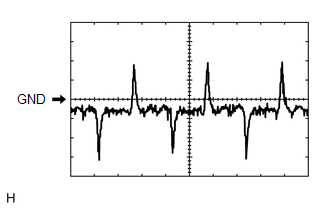
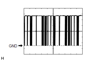
G36-21 (LOCK) - G36-2 (SG-2) |
B - W | A/C lock sensor signal |
- Engine running
- Blower switch: LO
- A/C switch: On
| Pulse generation
(See waveform 1) |
|
G36-24 (PRE) - G36-3 (SG-4) |
W - L | Air conditioner pressure sensor signal |
- Engine running
- Air conditioning system operating
- Refrigerant pressure: Abnormal pressure (more than 3025 kPa (30.8 kgf/cm2, 439 psi))
| 4.61 V or higher |
- Engine running
- Air conditioning system operating
- Refrigerant pressure: Abnormal pressure (less than 176 kPa (1.8 kgf/cm2, 26 psi))
| Below 0.74 V |
- Engine running
- Air conditioning system operating
- Refrigerant pressure: Normal pressure (less than 3025 kPa (30.8 kgf/cm2, 439 psi) and more than 176 kPa (1.8 kgf/cm2, 26 psi))
| 0.74 to 4.61 V |
|
G35-1 (B) - G35-4 (GND) |
LA-B - W-B | Power source (Back-up) |
Always | 11 to 14 V |
|
G35-2 (IG+) - G35-4 (GND) |
LA-GR - W-B | Power source (IG) |
Engine switch on (IG) |
11 to 14 V |
| Engine switch off |
Below 1 V |
|
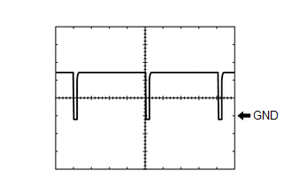
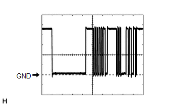
G35-3 (SOL+) - G35-4 (GND) |
R - W-B | Compressor solenoid operation signal |
- Engine running
- Blower switch: LO
- A/C switch: On
| Pulse generation
(See waveform 2) |
|
G35-4 (GND) - Body ground |
W-B - Body ground | Ground for main power supply |
Always | Below 1 V |
|
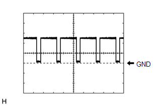
G35-6 (BLW) - G35-4 (GND) |
LG - W-B | Blower motor speed control signal |
- Engine switch on (IG)
- Blower switch: LO
| Pulse generation
(See waveform 3) |
|
G35-11 (CANH) - G35-12 (CANL) |
SB - W | CAN communication system |
CAN communication is performed |
Pulse generation |
|
G35-14 (LIN1) - G35-4 (GND) |
LG - W-B | LIN communication signal |
Engine switch on (IG) |
Pulse generation (See waveform 4) |
|
z8-2 (BUS G) - Body ground |
B - Body ground | Ground for BUS IC |
Always | Below 1 V |
|
z8-3 (BUS) - z8-2 (BUS G) |
L - B | BUS IC control signal |
Engine switch on (IG) |
Pulse generation (See waveform 5) |
|
z8-4 (B BUS) - z8-2 (BUS G) |
R - B | Power supply for BUS IC |
Engine switch off | 11 to 14 V |
|
z8-5 (SGA) - Body ground |
GR - Body ground | Ground for No. 1 cooler thermistor |
Always | Below 1 V |
|
z8-6 (TEA) - z8-5 (SGA) |
GR - GR | No. 1 cooler thermistor signal |
- Engine switch on (IG)
- Evaporator temperature: 0°C (32°F)
| 1.7 to 2.1 V |
- Engine switch on (IG)
- Evaporator temperature: 15°C (59°F)
| 0.9 to 1.3 V |