REMOVAL CAUTION / NOTICE / HINT The necessary procedures (adjustment, calibration, initialization, or registration) that must be performed after parts are removed and installed, or replaced during air conditioning unit removal/installation are shown below. Necessary Procedure After Parts Removed/Installed/Replaced
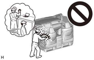
CAUTION: Some of these service operations affect the SRS airbag system. Read the precautionary notices concerning the SRS airbag system before servicing. Click here
 PROCEDURE 1. PRECAUTION NOTICE: Make sure to select face mode before disconnecting the cable from the negative (-) battery terminal. 2. RECOVER REFRIGERANT FROM REFRIGERATION SYSTEM Click here
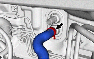
3. REMOVE WINDSHIELD WIPER MOTOR AND LINK ASSEMBLY Click here 4. REMOVE FRONT CENTER UPPER SUSPENSION BRACE SUB-ASSEMBLY Click here 5. DISCONNECT OUTLET HEATER WATER HOSE
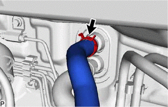
6. DISCONNECT INLET HEATER WATER HOSE
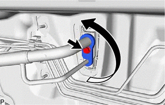
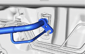
7. DISCONNECT NO. 2 AIR CONDITIONING TUBE AND ACCESSORY ASSEMBLY
(c) Remove the 2 O-rings from the No. 2 air conditioning tube and accessory assembly. NOTICE: Seal the openings of the disconnected parts using vinyl tape to prevent entry of moisture and foreign matter. 8. REMOVE FRONT SEAT ASSEMBLY LH Click here
9. REMOVE FRONT SEAT ASSEMBLY RH HINT: Use the same procedure as for the LH side. 10. REMOVE TRANSMISSION FLOOR SHIFT ASSEMBLY Click here 11. REMOVE STEERING COLUMN ASSEMBLY for Manual Tilt and Manual Telescopic Steering Column: Click here
for Power Tilt and Power Telescopic Steering Column: Click here 12. REMOVE INSTRUMENT PANEL SAFETY PAD SUB-ASSEMBLY Click here 13. REMOVE ECU INTEGRATION BOX RH Click here 14. REMOVE STEREO COMPONENT EQUALIZER ASSEMBLY (w/ Active Noise Control System) Click here 15. REMOVE DCM (TELEMATICS TRANSCEIVER) WITH BRACKET Click here 16. REMOVE NO. 1 CLEARANCE WARNING BUZZER (w/ Intelligent Parking Assist System) Click here 17. REMOVE DRIVING SUPPORT ECU ASSEMBLY Click here 18. REMOVE COOLER (ROOM TEMP. SENSOR) THERMISTOR Click here 19. REMOVE ACCELERATOR PEDAL PAD Click here 20. REMOVE ACCELERATOR PEDAL Click here 21. REMOVE REAR NO. 2 AIR DUCT Click here 22. REMOVE REAR NO. 1 AIR DUCT Click here 23. REMOVE REAR NO. 4 AIR DUCT Click here 24. REMOVE REAR NO. 3 AIR DUCT Click here 25. REMOVE FLOOR CARPET BRACKET RH Click here 26. REMOVE FLOOR CARPET BRACKET LH Click here 27. REMOVE NO. 1 CONSOLE BOX DUCT Click here 28. REMOVE NO. 3 DASH PANEL INSULATOR PAD Click here 29. REMOVE NO. 1 INSTRUMENT PANEL BRACE SUB-ASSEMBLY
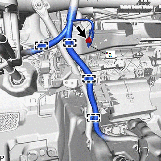
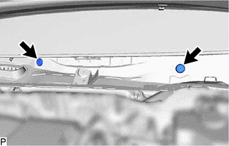
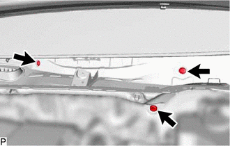
(b) Disengage each clamp. (c) Remove the bolt, screw, nut and No. 1 instrument panel brace sub-assembly. 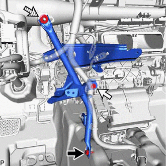
30. REMOVE NO. 2 INSTRUMENT PANEL BRACE SUB-ASSEMBLY Click here 31. REMOVE NO. 3 INSTRUMENT PANEL TO COWL BRACE SUB-ASSEMBLY Click here 32. REMOVE INSTRUMENT PANEL JUNCTION BLOCK ASSEMBLY WITH MAIN BODY ECU Click here 33. REMOVE INSTRUMENT PANEL REINFORCEMENT ASSEMBLY WITH AIR CONDITIONER UNIT ASSEMBLY NOTICE:
(a) Disconnect the connector. 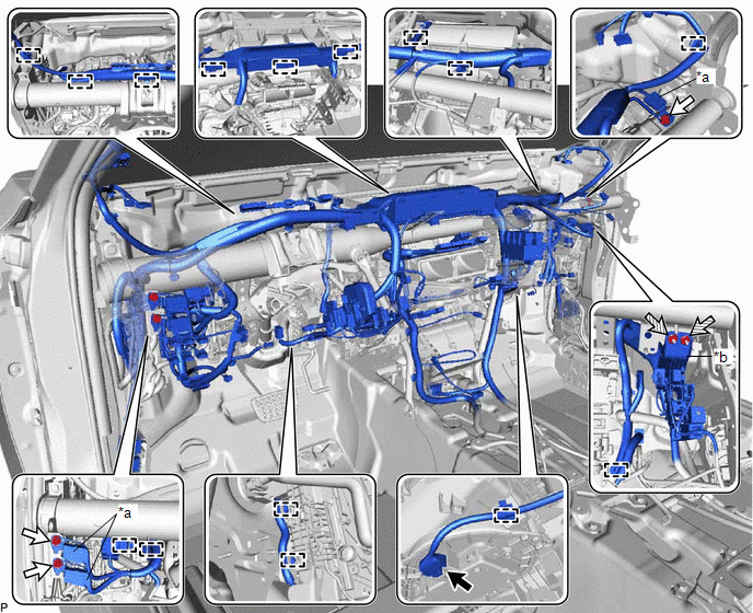
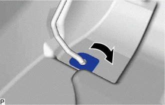
(b) Remove the 3 bolts and disconnect the 3 earth wires. (c) Remove the 2 nuts and disconnect the connector holder. (d) Disengage each clamp. (e) Push down the part (A) in the direction indicated by the arrow (1), to release the lock, and then move the lock lever in the direction indicated by the arrow (2) shown in the illustration to disconnect the connector. 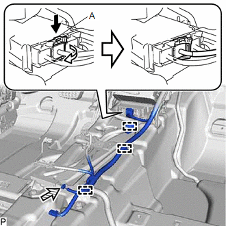
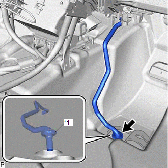
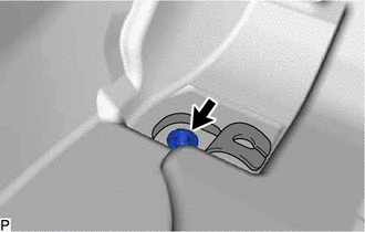
NOTICE: When disconnecting any airbag connector, take care not to damage the airbag wire harness. (f) Disconnect the connector. (g) Disengage each clamp to separate the instrument panel wire.
(m) Remove the 4 bolts (A). 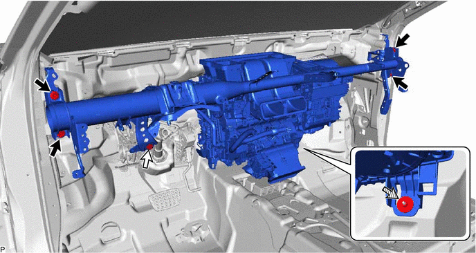
(n) Remove the bolt (B) and disconnect the brake pedal assembly. (o) Remove the nut. (p) Disengage each clamp. 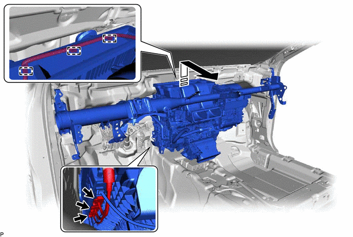
(q) Disconnect each connector. (r) Remove the instrument panel reinforcement assembly with air conditioner unit assembly as shown in the illustration. 34. REMOVE AIR CONDITIONER UNIT ASSEMBLY Click here
| ||||||||||||||||||||||||||||||||||||||||||||||||||||||||||||||||||||||||||||||||||||||||||||||||||||||||
Toyota Avalon (XX50) 2019-2022 Service & Repair Manual > Lighting System(for Hv Model With Cornering Light): Parts Location
PARTS LOCATION ILLUSTRATION *1 SIDE TURN SIGNAL LIGHT ASSEMBLY LH *2 SIDE TURN SIGNAL LIGHT ASSEMBLY RH *3 HEADLIGHT ASSEMBLY LH - HEADLIGHT ECU SUB-ASSEMBLY LH *4 HEADLIGHT ASSEMBLY RH - HEADLIGHT ECU SUB-ASSEMBLY RH *5 FORWARD RECOGNITION CAMERA *6 PARKING BRAKE ECU (BRAKE ACTUATOR ASSEMBLY) *7 SK ...