Toyota Avalon (XX50) 2019-2022 Service & Repair Manual: Installation

INSTALLATION

PROCEDURE

1. ADJUST COMPRESSOR OIL

(a) When replacing the compressor assembly with magnetic clutch with a new one:

(1) Remove the drain bolt (seal washer) from a new compressor assembly with magnetic clutch.

*a

Drain Bolt (Seal Washer)

(2) Gradually discharge the inert gas from the service valve of the new compressor assembly with magnetic clutch. Then drain the following amount of oil from the new compressor before installation so that the amount of oil contained in it is the same as that in the compressor to be replaced.

HINT:

New compressors are filled with sufficient oil for the whole air conditioning system. Therefore, it is necessary to drain oil from the new compressor to compensate for oil remaining in the condenser and cooling unit.

Standard:

(The amount of compressor oil inside a new compressor assembly with magnetic clutch: 70 (+15) cc (2.37 (+0.51) fl.oz)) - (The amount of compressor oil remaining in the removed compressor assembly with magnetic clutch) = The amount of compressor oil to be removed when replacing the compressor assembly with magnetic clutch.

NOTICE:

  • When A + 60 cc (2.03 fl.oz) exceeds the standard oil fill volume specified for the compressor by part number, install the compressor without adjusting the oil volume.

    Example:

    If A = 45 cc (1.52 fl.oz), A + 60 cc (2.03 fl.oz) = 105 cc (3.55 fl.oz). If the standard volume is 70 (+15) cc (2.37 (+0.51) fl.oz)), install the compressor as is.

  • If the amount of compressor oil remaining in the removed compressor assembly with magnetic clutch is excessively low, check for compressor oil leaks.
  • Make sure to use ND-OIL 12 or equivalent compressor oil.

*a

Removed Compressor

*b

Amount of oil to be drained from removed compressor assembly with magnetic clutch

*c

Amount of oil remaining in the reserve chamber (60 cc (2.03 fl.oz))

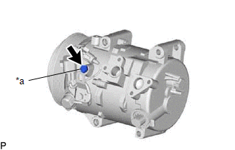
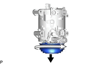
(3) Install the drain bolt (seal washer).

Torque:

30 N·m {306 kgf·cm, 22 ft·lbf}

(b) If draining the oil is difficult, drain the oil using the following procedure:

(1) Remove the suction seal cap.

(2) Lightly shake the compressor assembly with magnetic clutch with the suction port facing down, and drain the oil (*1).

NOTICE:

Do not allow the pulley to come into contact with the compressor oil.

(c) With the pulley facing down, rotate the pulley as shown in the illustration 10 times at a rate of approximately once every 2 seconds (*2).

CAUTION:

If the pulley is rotated, refrigerant or oil may spray out. Thus, keep your face away from the compressor port.

(d) Rotate the pulley once as shown in the illustration while quickly turning the compressor up (*3).

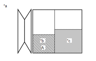
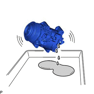
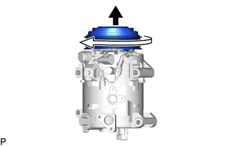
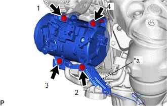
(e) Perform step (*1) and drain the oil (*4).

(f) Drain the oil by repeating steps (*2) to (*4) approximately 5 times.

2. INSTALL COMPRESSOR ASSEMBLY WITH MAGNETIC CLUTCH

(a) for Type A:

(1) Using an E8 "TORX" socket wrench, temporarily install the compressor assembly with magnetic clutch with the 2 stud bolts.

Torque:

10 N·m {102 kgf·cm, 7 ft·lbf}

(2) Install the compressor assembly with magnetic clutch and bracket with the 2 bolts and 2 nuts.

*a

Bracket

Bolt

Nut

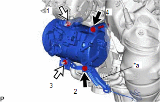
Torque:

24.5 N·m {250 kgf·cm, 18 ft·lbf}

HINT:

Tighten the bolts and nuts in the order shown in the illustration.

(b) for Type B:

(1) Install the compressor assembly with magnetic clutch and bracket with the 4 bolts.

Torque:

24.5 N·m {250 kgf·cm, 18 ft·lbf}

HINT:

Tighten the bolts in the order shown in the illustration.

*a

Bracket

(c) Engage each clamp.

(d) Connect each connector.

3. CONNECT SUCTION HOSE SUB-ASSEMBLY

(a) Remove the vinyl tape from the suction hose sub-assembly.

(b) Sufficiently apply compressor oil to a new O-ring and the fitting surface of the suction hose sub-assembly.

Compressor Oil:

ND-OIL 12 or equivalent

(c) Install the O-ring to the suction hose sub-assembly.

(d) Connect the suction hose sub-assembly to the compressor assembly with magnetic clutch with the bolt.

Torque:

9.8 N·m {100 kgf·cm, 87 in·lbf}

4. CONNECT NO. 1 COOLER REFRIGERANT DISCHARGE HOSE SUB-ASSEMBLY

(a) Remove the vinyl tape from the No. 1 cooler refrigerant discharge hose sub-assembly.

(b) Sufficiently apply compressor oil to a new O-ring and the fitting surface of the No. 1 cooler refrigerant discharge hose sub-assembly.

Compressor Oil:

ND-OIL 12 or equivalent

(c) Install the O-ring to the No. 1 cooler refrigerant discharge hose sub-assembly.

(d) Connect the No. 1 cooler refrigerant discharge hose sub-assembly to the compressor assembly with magnetic clutch with the bolt.

Torque:

9.8 N·m {100 kgf·cm, 87 in·lbf}

5. INSTALL V-RIBBED BELT

Click here

6. INSTALL RADIATOR ASSEMBLY

Click here

7. CHARGE AIR CONDITIONING SYSTEM WITH REFRIGERANT

Click here

8. WARM UP ENGINE

Click here

9. INSPECT FOR REFRIGERANT LEAK

Click here

    Inspection

    Reassembly

    See More:

    Toyota Avalon (XX50) 2019-2022 Service & Repair Manual > Automatic Transaxle System: System Voltage Circuit Short to Ground or Open (P056014)
    DESCRIPTION The battery supplies electricity to the ECM even when the engine switch is off. This power allows the ECM to store data such as DTC history and freeze frame data. If the battery voltage falls below a minimum level, the stored ECM data will be cleared and the ECM will determine that there ...

    Toyota Avalon (XX50) 2019-2022 Owners Manual

    Toyota Avalon (XX50) 2019-2022 Service & Repair Manual

    © 2024 Copyright www.tavalon.net
    0.0197