REMOVAL CAUTION / NOTICE / HINT The necessary procedures (adjustment, calibration, initialization, or registration) that must be performed after parts are removed and installed, or replaced during compressor assembly with magnetic clutch removal/installation are shown below. Necessary Procedure After Parts Removed/Installed/Replaced
PROCEDURE 1. RECOVER REFRIGERANT FROM REFRIGERATION SYSTEM Click here
2. REMOVE V-RIBBED BELT Click here
3. REMOVE RADIATOR ASSEMBLY Click here
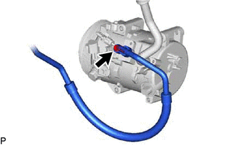
4. DISCONNECT NO. 1 COOLER REFRIGERANT DISCHARGE HOSE SUB-ASSEMBLY
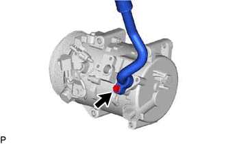
(b) Remove the O-ring from the No. 1 cooler refrigerant discharge hose sub-assembly. NOTICE: Seal the openings of the disconnected parts using vinyl tape to prevent moisture and foreign matter from entering them. 5. DISCONNECT SUCTION HOSE SUB-ASSEMBLY
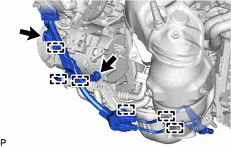
(b) Remove the O-ring from the suction hose sub-assembly. NOTICE: Seal the openings of the disconnected parts using vinyl tape to prevent moisture and foreign matter from entering them. 6. REMOVE COMPRESSOR ASSEMBLY WITH MAGNETIC CLUTCH
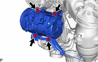
(b) Disengage each clamp. (c) for Type A: (1) Remove the 2 bolts and 2 nuts, and separate the bracket. 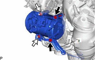
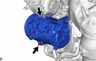
(d) for Type B:
(e) Remove the compressor assembly with magnetic clutch. | ||||||||||||||||||||||||||||||||||||||||||||
Toyota Avalon (XX50) 2019-2022 Service & Repair Manual > Intelligent Clearance Sonar System(for Gasoline Model): CAN Communication Failure (Message Registry) (U1000)
DESCRIPTION When the clearance warning ECU assembly determines that the CAN communication circuit is malfunctioning during self diagnosis, DTC U1000 is stored. DTC No. Detection Item DTC Detection Condition Trouble Area U1000 CAN Communication Failure (Message Registry) CAN communication circuit mal ...

 for Initialization