INSTALLATION PROCEDURE 1. INSTALL COOLER CONDENSER ASSEMBLY (a) Engage the 2 guides and 2 claws to install the cooler condenser assembly as shown in the illustration. 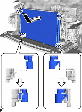
NOTICE: Do not damage the cooler condenser assembly or radiator assembly when installing the cooler condenser assembly. HINT: If a new cooler condenser assembly is installed, add compressor oil to the cooler condenser assembly as follows. Capacity: Add 40 cc (1.35 fl. oz)
2. INSTALL UPPER RADIATOR SUPPORT SUB-ASSEMBLY for A25A-FXS: Click here
for 2GR-FKS: Click here
3. CONNECT AIR CONDITIONING TUBE AND ACCESSORY ASSEMBLY (a) Remove the vinyl tape from the cooler condenser assembly and air conditioning tube and accessory assembly.
(c) Sufficiently apply compressor oil to 2 new O-rings and the fitting surfaces of the air conditioning tube and accessory assembly.
(d) Install the 2 O-rings to the air conditioning tube and accessory assembly. NOTICE: Keep the O-rings and O-ring fitting surfaces free from foreign matter. (e) Connect the air conditioning tube and accessory assembly to the cooler condenser assembly. 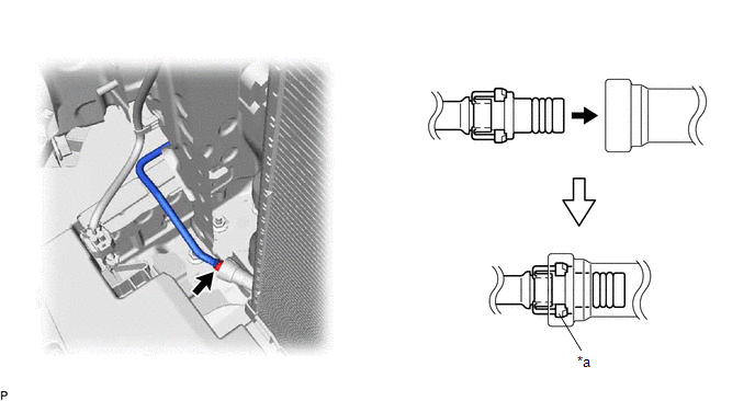
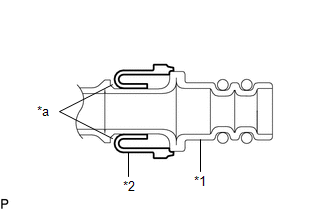
NOTICE: Connect the parts by holding the pipe, not the piping clamp. (f) Securely insert the piping clamp to the point where the large diameter section of the piping clamp is covered by the cooler condenser assembly. HINT:
4. CONNECT NO. 1 COOLER REFRIGERANT DISCHARGE HOSE SUB-ASSEMBLY (a) Remove the vinyl tape from the No. 1 cooler refrigerant discharge hose sub-assembly and cooler condenser assembly. (b) Sufficiently apply compressor oil to a new O-ring and the fitting surface of the No. 1 cooler refrigerant discharge hose sub-assembly.
(c) Install the O-ring to the No. 1 cooler refrigerant discharge hose sub-assembly. HINT: Keep the O-ring and O-ring fitting surface free from foreign matter. (d) Connect the No. 1 cooler refrigerant discharge hose sub-assembly to the cooler condenser assembly with the bolt. Torque: 5.4 N·m {55 kgf·cm, 48 in·lbf} 5. INSTALL NO. 1 RADIATOR AIR GUIDE RH (a) Engage the guide and claw to install the No. 1 radiator air guide RH as shown in the illustration. 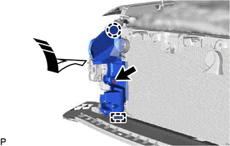
(b) Install the clip. 6. INSTALL THERMISTOR ASSEMBLY (for 2GR-FKS) Click here 7. INSTALL FRONT RADIATOR SIDE AIR GUIDE PLATE RH (for 2GR-FKS) Click here 8. INSTALL NO. 1 RADIATOR AIR GUIDE LH (a) Engage the guide and claw to install the No. 1 radiator air guide LH as shown in the illustration. 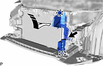
(b) Install the clip. 9. INSTALL HOOD LOCK ASSEMBLY Click here
10. INSTALL INLET AIR CLEANER ASSEMBLY (for A25A-FXS) Click here 11. INSTALL INLET AIR CLEANER ASSEMBLY (for 2GR-FKS) Click here 12. INSTALL UPPER RADIATOR MOUNTING BRACKET for A25A-FXS: Click here for 2GR-FKS: Click here 13. INSTALL FRONT BUMPER REINFORCEMENT Click here 14. INSTALL FRONT BUMPER ENERGY ABSORBER Click here 15. INSTALL NO. 2 FRONT BUMPER ENERGY ABSORBER Click here 16. INSTALL HEADLIGHT ASSEMBLY LH Click here 17. INSTALL HEADLIGHT ASSEMBLY RH HINT: Use the same procedure as for the LH side. 18. INSTALL RADIATOR SHUTTER SUB-ASSEMBLY (for A25A-FXS) Click here 19. CHARGE AIR CONDITIONING SYSTEM WITH REFRIGERANT Click here 20. WARM UP ENGINE (for Gasoline Model) Click here 21. WARM UP COMPRESSOR (for HV Model) Click here 22. INSPECT FOR REFRIGERANT LEAK Click here 23. ADJUST HOOD SUB-ASSEMBLY Click here |
Toyota Avalon (XX50) 2019-2022 Service & Repair Manual > Power Steering System(for Hv Model): Assist Map Number Mismatch (C1582)
DESCRIPTION When an incorrect hybrid vehicle control ECU, main body ECU (multiplex network body ECU) or skid control ECU (brake booster with master cylinder assembly) is installed after the assist map has been written to the power steering ECU (rack and pinion power steering gear assembly), DTC C158 ...