REMOVAL CAUTION / NOTICE / HINT
The
necessary procedures (adjustment, calibration, initialization or
registration) that must be performed after parts are removed and
installed, or replaced during No. 1 cooler thermistor
removal/installation are shown below. Necessary Procedure After Parts Removed/Installed/Replaced (for Gasoline Model) |
Replaced Part or Performed Procedure |
Necessary Procedure | Effect/Inoperative Function when Necessary Procedure not Performed |
Link | |
*: When performing learning using the Techstream.
Click here  | |
Disconnect cable from negative battery terminal |
Perform steering sensor zero point calibration |
Lane Departure Alert System (w/ Steering Control) |
| |
Pre-collision System | |
Intelligent Clearance Sonar System* | |
Lighting System (for Gasoline Model with Cornering Light) | |
Memorize steering angle neutral point |
Parking Assist Monitor System |
| |
Panoramic View Monitor System |
| |
Steering sensor | Steering angle zero point learning (Initialize intelligent clearance sonar system) |
- Intelligent Clearance Sonar System
- Intuitive Parking Assist System
|
|
- Steering angle neutral point (Initialize parking assist monitor system)
- Steering angle setting
| Parking Assist Monitor System |
for Initialization
for Calibration | |
Steering angle zero point learning (Initialize panoramic view monitor system) |
Panoramic View Monitor System |
for Initialization
for Calibration | |
Front passenger seat | Zero point calibration (Occupant classification system) |
- Occupant classification system
- Passenger airbag ON/OFF indicator
- Airbag system (Front passenger side)
- Seat belt warning system (Front passenger)
|
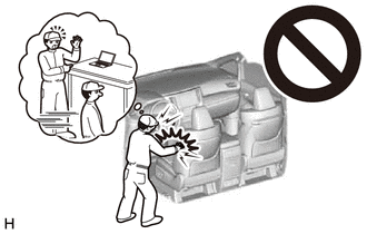
| CAUTION:
Some
of these service operations affect the SRS airbag system. Read the
precautionary notices concerning the SRS airbag system before servicing.
 Click here
Necessary Procedure After Parts Removed/Installed/Replaced (for HV Model) |
Replaced Part or Performed Procedure |
Necessary Procedure | Effect/Inoperative Function When Necessary Procedures are not Performed |
Link | |
*: When performing learning using the Techstream.
Click here | |
Disconnect cable from negative auxiliary battery terminal |
Perform steering sensor zero point calibration |
Lane Departure Alert System (w/ Steering Control) |
| |
Pre-collision System | |
Intelligent Clearance Sonar System* | |
Lighting System (for HV Model with Cornering Light) | |
Memorize steering angle neutral point |
Parking Assist Monitor System |
| |
Panoramic View Monitor System |
| |
Steering sensor | Steering angle zero point learning (Initialize intelligent clearance sonar system) |
- Intelligent Clearance Sonar System
- Intuitive Parking Assist System
|
|
- Steering angle zero point learning (Initialize parking assist monitor system)
- Steering angle setting
| Parking Assist Monitor System |
for Initialization
for Calibration | |
Steering angle zero point learning (Initialize panoramic view monitor system) |
Panoramic View Monitor System |
for Initialization
for Calibration | |
Front passenger seat | Zero point calibration (Occupant classification system) |
- Occupant classification system
- Passenger airbag ON/OFF indicator
- Airbag system (Front passenger side)
- Seat belt warning system (Front passenger)
|
| CAUTION:
Some
of these service operations affect the SRS airbag system. Read the
precautionary notices concerning the SRS airbag system before servicing.
Click here
PROCEDURE 1. REMOVE BLOWER ASSEMBLY
Click here 2. REMOVE NO. 4 HEATER TO REGISTER DUCT SUB-ASSEMBLY
Click here 3. REMOVE NO. 2 AIR DUCT SUB-ASSEMBLY
Click here 4. REMOVE AIR CONDITIONING HARNESS ASSEMBLY
for 2GR-FKS: Click here for A25A-FXS:
Click here 5. REMOVE NO. 1 AIR CONDITIONING RADIATOR DAMPER SERVO SUB-ASSEMBLY
Click here 6. REMOVE HEATER PIPE GROMMET
Click here 7. REMOVE HEATER CLAMP
Click here 8. REMOVE HEATER RADIATOR UNIT SUB-ASSEMBLY
Click here 9. REMOVE COOLING UNIT PARTS
Click here 10. REMOVE COOLER EXPANSION VALVE
Click here 11. REMOVE NO. 1 COOLER EVAPORATOR SUB-ASSEMBLY
for 2GR-FKS: Click here for A25A-FXS:
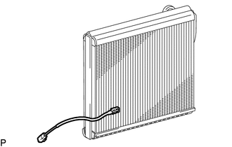
Click here 12. REMOVE NO. 1 COOLER THERMISTOR
(a) for 2GR-FKS: | (1) Remove the No. 1 cooler thermistor. |
|
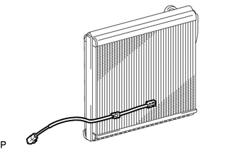
(b) for A25A-FXS: | (1) Remove the No. 1 cooler thermistor. |
| |