Components COMPONENTS ILLUSTRATION 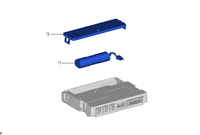
Installation INSTALLATION PROCEDURE 1. INSTALL BACK-UP BATTERY (a) Install the back-up battery shown in the illustration. 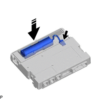
NOTICE: Make sure that the back-up battery is securely installed. (b) Connect the connector. NOTICE: Make sure that the connector is connected securely. (c) Engage the 2 claws to install the battery cover as shown in the illustration. 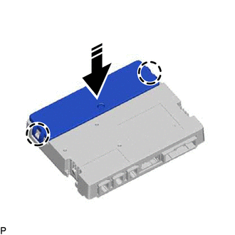
NOTICE: Make sure that the battery cover is securely installed. 2. INSTALL DCM (TELEMATICS TRANSCEIVER) Click here 3. PERFORM INITIALIZATION for Gasoline Model: Click here for HV Model: Click here
Removal REMOVAL CAUTION / NOTICE / HINT The necessary procedures (adjustment, calibration, initialization, or registration) that must be performed after parts are removed and installed, or replaced during back-up battery removal/installation are shown below. Necessary Procedure After Parts Removed/Installed/Replaced (for Gasoline Model)
PROCEDURE 1. REMOVE DCM (TELEMATICS TRANSCEIVER) Click here
2. REMOVE BACK-UP BATTERY (a) Disengage the 2 claws and remove the battery cover as shown in the illustration. 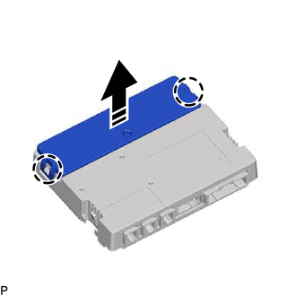
(b) Disconnect the connector and remove the back-up battery as shown in the illustration. 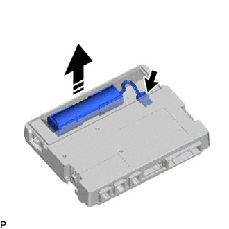
|
Toyota Avalon (XX50) 2019-2022 Service & Repair Manual > Window Defogger System(for Hv Model): How To Proceed With Troubleshooting
CAUTION / NOTICE / HINT HINT: Use the following procedure to troubleshoot the window defogger system. *: Use the Techstream. PROCEDURE 1. VEHICLE BROUGHT TO WORKSHOP NEXT 2. CUSTOMER PROBLEM ANALYSIS HINT: In troubleshooting, confirm that the problem symptoms have been accurately identified. Preconc ...


