DESCRIPTION The main body ECU (multiplex network body ECU) controls the operation of the following lights:
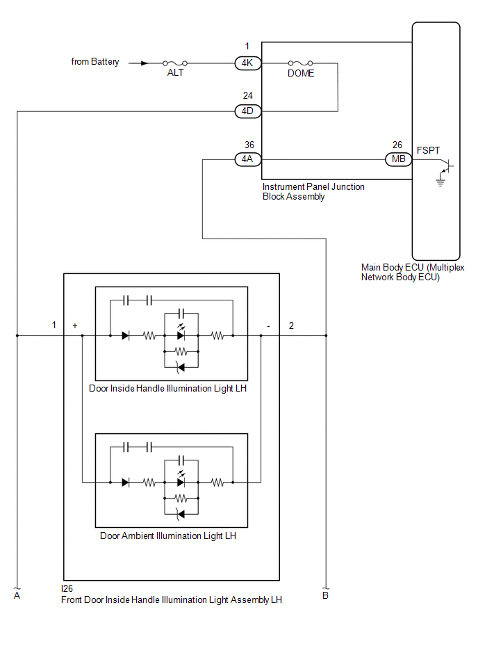
- Front Door Inside Handle Illumination Light Assembly LH
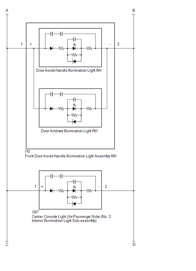
- Front Door Inside Handle Illumination Light Assembly RH
- Center Console Light (for Passenger Side) (No. 2 Interior Illumination Light Sub-assembly)
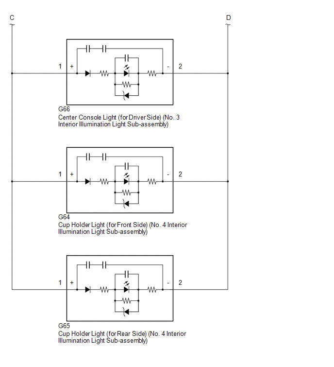
- Center Console Light (for Driver Side) (No. 3 Interior Illumination Light Sub-assembly)
- Cup Holder Light (for Front Side) (No. 4 Interior Illumination Light Sub-assembly)
- Cup Holder Light (for Rear Side) (No. 4 Interior Illumination Light Sub-assembly)
WIRING DIAGRAM
 CAUTION / NOTICE / HINT
NOTICE:
- Inspect the fuses for circuits related to this system before performing the following procedure.
- Before replacing the main body ECU (multiplex network body ECU), refer to Registration.
Click here 
PROCEDURE |
1. | PERFORM ACTIVE TEST USING TECHSTREAM |
(a) Connect the Techstream to the DLC3. (b) Turn the engine switch on (IG).
(c) Turn the Techstream on. (d) Enter the following menus: Body Electrical / Main Body / Active Test.
(e) Perform the Active Test according to the display on the Techstream. Body Electrical > Main Body > Active Test
|
Tester Display | Measurement Item |
Control Range | Diagnostic Note | |
Fr Foot Light |
- Front door inside handle illumination light assembly
- Center console light (for passenger side) (No. 2 interior illumination light sub-assembly)
- Center console light (for driver side) (No. 3 interior illumination light sub-assembly)
- Cup holder light (No. 4 interior illumination light sub-assembly)
| OFF or ON |
Preconditions for using the Active Test to check dimmer controlled illumination:
- Engine switch on (IG)
- Ambient illumination lights turned off using the mood switch
| Body Electrical > Main Body > Active Test
|
Tester Display | | Fr Foot Light |
OK: Front door inside handle illumination lights, center console lights and cup holder lights come on.
|
Result | Proceed to | |
OK | A | |
NG (Front door inside handle illumination light LH does not come on) |
B | | NG (Front door inside handle illumination light RH does not come on) |
C | | NG (Center console light (for passenger side) does not come on) |
D | | NG (Center console light (for driver side) does not come on) |
E | | NG (Cup holder light (for front side) does not come on) |
F | | NG (Cup holder light (for rear side) does not come on) |
G | | NG (Front door inside handle illumination lights, center console lights and cup holder lights do not come on) |
H |
| A |
 | USE SIMULATION METHOD TO CHECK |
| C |
| GO TO STEP 4 |
| D |
| GO TO STEP 6 |
| E |
| GO TO STEP 8 |
| F |
| GO TO STEP 10 |
| G |
| GO TO STEP 12 |
| H |
| GO TO STEP 14 |
|
B |
 | |
| 2. |
INSPECT FRONT DOOR INSIDE HANDLE ILLUMINATION LIGHT ASSEMBLY LH |
(a) Remove the front door inside handle illumination light assembly LH.
Click here (b) Inspect the front door inside handle illumination light assembly LH.
Click here
| NG |
| REPLACE FRONT DOOR INSIDE HANDLE ILLUMINATION LIGHT ASSEMBLY LH |
|
OK | |
| |
| 3. |
CHECK HARNESS AND CONNECTOR (INSTRUMENT PANEL JUNCTION BLOCK ASSEMBLY - FRONT DOOR INSIDE HANDLE ILLUMINATION LIGHT ASSEMBLY LH) |
(a) Disconnect the 4A and 4D instrument panel junction block assembly connector.
(b) Measure the resistance according to the value(s) in the table below.
Standard Resistance: |
Tester Connection | Condition |
Specified Condition | |
4D-24 - I26-1 (+) | Always |
Below 1 Ω | |
4A-36 - I26-2 (-) | Always |
Below 1 Ω |
| OK |
| USE SIMULATION METHOD TO CHECK |
| NG |
| REPAIR OR REPLACE HARNESS OR CONNECTOR |
| 4. |
INSPECT FRONT DOOR INSIDE HANDLE ILLUMINATION LIGHT ASSEMBLY RH |
(a) Remove the front door inside handle illumination light assembly RH.
Click here (b) Inspect the front door inside handle illumination light assembly RH.
Click here
| NG |
| REPLACE FRONT DOOR INSIDE HANDLE ILLUMINATION LIGHT ASSEMBLY RH |
|
OK | |
| |
| 5. |
CHECK HARNESS AND CONNECTOR (INSTRUMENT PANEL JUNCTION BLOCK ASSEMBLY - FRONT DOOR INSIDE HANDLE ILLUMINATION LIGHT ASSEMBLY RH) |
(a) Disconnect the 4A and 4D instrument panel junction block assembly connector.
(b) Measure the resistance according to the value(s) in the table below.
Standard Resistance: |
Tester Connection | Condition |
Specified Condition | |
4D-24 - I10-1 (+) | Always |
Below 1 Ω | |
4A-36 - I10-2 (-) | Always |
Below 1 Ω |
| OK |
| USE SIMULATION METHOD TO CHECK |
| NG |
| REPAIR OR REPLACE HARNESS OR CONNECTOR |
| 6. |
INSPECT CENTER CONSOLE LIGHT (for Passenger Side) (NO. 2 INTERIOR ILLUMINATION LIGHT SUB-ASSEMBLY) |
(a) Remove the center console light (for passenger side) (No. 2 interior illumination light sub-assembly).
Click here (b) Inspect the center console light (for passenger side) (No. 2 interior illumination light sub-assembly).
Click here
| NG |
| REPLACE CENTER CONSOLE LIGHT (for Passenger Side) (NO. 2 INTERIOR ILLUMINATION LIGHT SUB-ASSEMBLY) |
|
OK | |
| |
| 7. |
CHECK HARNESS AND CONNECTOR (INSTRUMENT PANEL JUNCTION BLOCK ASSEMBLY - CENTER CONSOLE LIGHT (for Passenger Side)) |
(a) Disconnect the 4A and 4D instrument panel junction block assembly connector.
(b) Measure the resistance according to the value(s) in the table below.
Standard Resistance: |
Tester Connection | Condition |
Specified Condition | |
4D-24 - G67-1 (+) | Always |
Below 1 Ω | |
4A-36 - G67-2 (-) | Always |
Below 1 Ω |
| OK |
| USE SIMULATION METHOD TO CHECK |
| NG |
| REPAIR OR REPLACE HARNESS OR CONNECTOR |
| 8. |
INSPECT CENTER CONSOLE LIGHT (for Driver Side) (NO. 3 INTERIOR ILLUMINATION LIGHT SUB-ASSEMBLY) |
(a) Remove the center console light (for driver side) (No. 3 interior illumination light sub-assembly).
Click here (b) Inspect the center console light (for driver side) (No. 3 interior illumination light sub-assembly).
Click here
| NG |
| REPLACE CENTER CONSOLE LIGHT (for Driver Side) (NO. 3 INTERIOR ILLUMINATION LIGHT SUB-ASSEMBLY) |
|
OK | |
| |
| 9. |
CHECK HARNESS AND CONNECTOR (INSTRUMENT PANEL JUNCTION BLOCK ASSEMBLY - CENTER CONSOLE LIGHT (for Driver Side)) |
(a) Disconnect the 4A and 4D instrument panel junction block assembly connector.
(b) Measure the resistance according to the value(s) in the table below.
Standard Resistance: |
Tester Connection | Condition |
Specified Condition | |
4D-24 - G66-1 (+) | Always |
Below 1 Ω | |
4A-36 - G66-2 (-) | Always |
Below 1 Ω |
| OK |
| USE SIMULATION METHOD TO CHECK |
| NG |
| REPAIR OR REPLACE HARNESS OR CONNECTOR |
| 10. |
INSPECT CUP HOLDER LIGHT (for Front Side) (NO. 4 INTERIOR ILLUMINATION LIGHT SUB-ASSEMBLY) |
(a) Remove the cup holder light (for front side) (No. 4 interior illumination light sub-assembly).
Click here (b) Inspect the cup holder light (for front side) (No. 4 interior illumination light sub-assembly).
Click here
| NG |
| REPLACE CUP HOLDER LIGHT (for Front Side) (NO. 4 INTERIOR ILLUMINATION LIGHT SUB-ASSEMBLY) |
|
OK | |
| |
| 11. |
CHECK HARNESS AND CONNECTOR (INSTRUMENT PANEL JUNCTION BLOCK ASSEMBLY - CUP HOLDER LIGHT (for Front Side)) |
(a) Disconnect the 4A and 4D instrument panel junction block assembly connector.
(b) Measure the resistance according to the value(s) in the table below.
Standard Resistance: |
Tester Connection | Condition |
Specified Condition | |
4D-24 - G64-1 (+) | Always |
Below 1 Ω | |
4A-36 - G64-2 (-) | Always |
Below 1 Ω |
| OK |
| USE SIMULATION METHOD TO CHECK |
| NG |
| REPAIR OR REPLACE HARNESS OR CONNECTOR |
| 12. |
INSPECT CUP HOLDER LIGHT (for Rear Side) (NO. 4 INTERIOR ILLUMINATION LIGHT SUB-ASSEMBLY) |
(a) Remove the cup holder light (for rear side) (No. 4 interior illumination light sub-assembly).
Click here (b) Inspect the cup holder light (for rear side) (No. 4 interior illumination light sub-assembly).
Click here
| NG |
| REPLACE CUP HOLDER LIGHT (for Rear Side) (NO. 4 INTERIOR ILLUMINATION LIGHT SUB-ASSEMBLY) |
|
OK | |
| |
| 13. |
CHECK HARNESS AND CONNECTOR (INSTRUMENT PANEL JUNCTION BLOCK ASSEMBLY - CUP HOLDER LIGHT (for Rear Side)) |
(a) Disconnect the 4A and 4D instrument panel junction block assembly connector.
(b) Measure the resistance according to the value(s) in the table below.
Standard Resistance: |
Tester Connection | Condition |
Specified Condition | |
4D-24 - G65-1 (+) | Always |
Below 1 Ω | |
4A-36 - G65-2 (-) | Always |
Below 1 Ω |
| OK |
| USE SIMULATION METHOD TO CHECK |
| NG |
| REPAIR OR REPLACE HARNESS OR CONNECTOR |
| 14. |
CHECK HARNESS AND CONNECTOR (POWER SOURCE - INSTRUMENT PANEL JUNCTION BLOCK ASSEMBLY) |
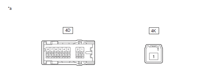
(a) Disconnect the 4K instrument panel junction block assembly connector.
(b) Measure the voltage according to the value(s) in the table below. Standard Voltage: |
Tester Connection | Condition |
Specified Condition | |
4K-1 - Body ground | Always |
11 to 14 V |
| NG |
| REPAIR OR REPLACE HARNESS OR CONNECTOR |
|
OK | |
| |
| 15. |
CHECK INSTRUMENT PANEL JUNCTION BLOCK ASSEMBLY |
|
*a | Component without harness connected
(Instrument Panel Junction Block Assembly) |
- | - |
(a) Disconnect the 4D instrument panel junction block assembly connector.
(b) Measure the resistance according to the value(s) in the table below.
Standard Resistance: |
Tester Connection | Condition |
Specified Condition | |
4D-24 - 4K-1 | Always |
Below 1 Ω |
| NG |
| REPLACE INSTRUMENT PANEL JUNCTION BLOCK ASSEMBLY |
|
OK | |
| |
| 16. |
CHECK HARNESS AND CONNECTOR (INSTRUMENT PANEL JUNCTION BLOCK ASSEMBLY - AMBIENT ILLUMINATION LIGHT) |
(a) Disconnect the I26 front door inside handle illumination light assembly LH connector.
(b) Disconnect the I10 front door inside handle illumination light assembly RH connector.
(c) Disconnect the G67 center console light (for passenger side) (No. 2 interior illumination light sub-assembly) connector.
(d) Disconnect the G66 center console light (for driver side) (No. 3 interior illumination light sub-assembly) connector.
(e) Disconnect the G64 cup holder light (for front side) (No. 4 interior illumination light sub-assembly) connector.
(f) Disconnect the G65 cup holder light (for rear side) (No. 4 interior illumination light sub-assembly) connector.
(g) Measure the resistance according to the value(s) in the table below.
Standard Resistance: |
Tester Connection | Condition |
Specified Condition | |
4D-24 - I26-1 (+) | Always |
Below 1 Ω | |
4D-24 - I10-1 (+) | Always |
Below 1 Ω | |
4D-24 - G64-1 (+) | Always |
Below 1 Ω | |
4D-24 - G65-1 (+) | Always |
Below 1 Ω | |
4D-24 - G66-1 (+) | Always |
Below 1 Ω | |
4D-24 - G67-1 (+) | Always |
Below 1 Ω | |
4A-36 - I26-2 (-) | Always |
Below 1 Ω | |
4A-36 - I10-2 (-) | Always |
Below 1 Ω | |
4A-36 - G64-2 (-) | Always |
Below 1 Ω | |
4A-36 - G65-2 (-) | Always |
Below 1 Ω | |
4A-36 - G66-2 (-) | Always |
Below 1 Ω | |
4A-36 - G67-2 (-) | Always |
Below 1 Ω | |
4D-24, I26-1 (+), I10-1 (+), G64-1 (+), G65-1 (+), G66-1 (+) or G67-1 (+) - Body ground |
Always | 10 kΩ or higher | |
4A-36, I26-2 (-), I10-2 (-), G64-2 (-), G65-2 (-), G66-2 (-) or G67-2 (-) - Body ground |
Always | 10 kΩ or higher |
| NG |
| REPAIR OR REPLACE HARNESS OR CONNECTOR |
|
OK | |
| |
| 17. |
INSPECT INSTRUMENT PANEL JUNCTION BLOCK ASSEMBLY |
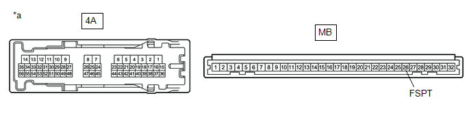
|
*a | Component without harness connected
(Instrument Panel Junction Block Assembly) |
- | - |
(a) Remove the main body ECU (multiplex network body ECU) from the instrument panel junction block assembly.
Click here (b) Measure the resistance according to the value(s) in the table below.
Standard Resistance: |
Tester Connection | Condition |
Specified Condition | |
4A-36 - MB-26 (FSPT) |
Always | Below 1 Ω |
| OK |
| REPLACE MAIN BODY ECU (MULTIPLEX NETWORK BODY ECU) |
| NG |
| REPLACE INSTRUMENT PANEL JUNCTION BLOCK ASSEMBLY | | 

