Toyota Avalon (XX50) 2019-2022 Service & Repair Manual: Turn Signal Light Circuit Current Below Threshold (B150718)

DESCRIPTION

This DTC is stored when the combination meter assembly detects an open in a front turn signal light circuit or rear turn signal light circuit.

HINT:

  • If there is an open in a front turn signal light circuit or rear turn signal light circuit, the turn signal lights on the side with the open circuit will blink faster than usual.
  • If there is an open in a side turn signal light circuit, DTC B150718 will not be stored.

DTC No.

Detection Item

DTC Detection Condition

Trouble Area

Memory

Note

B150718

Turn Signal Light Circuit Current Below Threshold

Diagnosis Condition:

  • Auxiliary battery voltage is 10 V or more

Malfunction Status:

  • Open in front turn signal light circuit
  • Open in rear turn signal light circuit
  • Harness or connector
  • Headlight assembly
  • Headlight ECU sub-assembly*
  • Rear combination light assembly
  • Rear light assembly*
  • Rear combination light socket and wire
  • Rear light cord*
  • Combination meter assembly

DTC stored

-

  • *: w/ Cornering Light

WIRING DIAGRAM

LH SIDE
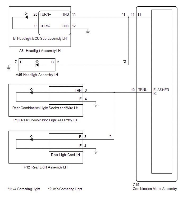
RH SIDE

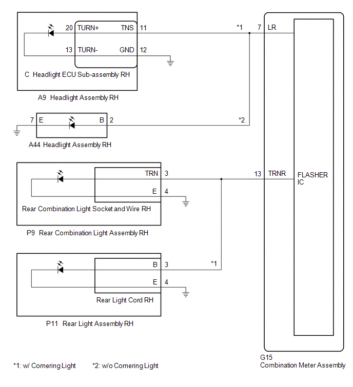
CAUTION / NOTICE / HINT

NOTICE:

When replacing the combination meter assembly, always replace it with a new one. If a combination meter assembly which was installed to another vehicle is used, the information stored in it will not match the information from the vehicle and a DTC may be stored.

PROCEDURE

1.

INSPECT LIGHTS

(a) Inspect the illumination of each turn signal light.

Result

Proceed to

Front turn signal light LH does not blink

A

Rear turn signal light LH does not blink

B

Front turn signal light RH does not blink

C

Rear turn signal light RH does not blink

D

B

GO TO STEP 8

C

GO TO STEP 18

D

GO TO STEP 24

A

2.

CONFIRM MODEL

(a) Choose the model to be inspected.

Result

Proceed to

w/ Cornering Light

A

w/o Cornering Light

B

B

GO TO STEP 6

A

3.

CHECK HARNESS AND CONNECTOR (HEADLIGHT ASSEMBLY LH - COMBINATION METER ASSEMBLY AND BODY GROUND)

(a) Disconnect the A8 headlight assembly LH connector.

(b) Disconnect the G15 combination meter assembly connector.

(c) Measure the resistance according to the value(s) in the table below.

Standard Resistance:

Tester Connection

Condition

Specified Condition

A8-11 (TNS) - G15-11 (LL)

Always

Below 1 Ω

A8-12 (GND) - Body ground

Always

Below 1 Ω

NG

REPAIR OR REPLACE HARNESS OR CONNECTOR

OK

4.

INSPECT HEADLIGHT ECU SUB-ASSEMBLY LH

*a

Component without harness connected

(Headlight ECU Sub-assembly LH)

-

-

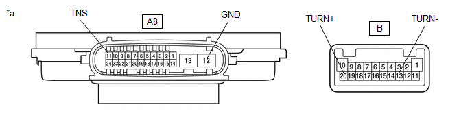
(a) Remove the headlight ECU sub-assembly LH.

Click here

(b) Measure the resistance according to the value(s) in the table below.

Standard Resistance:

Tester Connection

Condition

Specified Condition

B-20 (TURN+) - A8-11 (TNS)

Always

Below 1 Ω

B-13 (TURN-) - A8-12 (GND)

Always

Below 1 Ω

NG

REPLACE HEADLIGHT ECU SUB-ASSEMBLY LH

OK

5.

CHECK HEADLIGHT ASSEMBLY LH

(a) Connect the G15 combination meter assembly connector.

(b) Remove each headlight ECU sub-assembly, interchange the headlight assembly LH with RH and connect the connectors.

Click here

(c) Check that the front turn signal light operates normally.

OK:

Front turn signal light blinks.

OK

REPLACE HEADLIGHT ASSEMBLY LH

NG

REPLACE COMBINATION METER ASSEMBLY

6.

CHECK HARNESS AND CONNECTOR (HEADLIGHT ASSEMBLY LH - COMBINATION METER ASSEMBLY AND BODY GROUND)

(a) Disconnect the A45 headlight assembly LH connector.

(b) Disconnect the G15 combination meter assembly connector.

(c) Measure the resistance according to the value(s) in the table below.

Standard Resistance:

Tester Connection

Condition

Specified Condition

A45-2 (B) - G15-11 (LL)

Always

Below 1 Ω

A45-7 (E) - Body ground

Always

Below 1 Ω

NG

REPAIR OR REPLACE HARNESS OR CONNECTOR

OK

7.

CHECK HEADLIGHT ASSEMBLY LH

(a) Connect the G15 combination meter assembly connector.

(b) Interchange the headlight assembly LH with RH and connect the connectors.

Click here

(c) Check that the front turn signal light operates normally.

OK:

Front turn signal light blinks.

OK

REPLACE HEADLIGHT ASSEMBLY LH

NG

REPLACE COMBINATION METER ASSEMBLY

8.

CONFIRM MODEL

(a) Choose the model to be inspected.

Result

Proceed to

w/ Cornering Light

A

w/o Cornering Light

B

B

GO TO STEP 15

A

9.

CHECK HARNESS AND CONNECTOR (REAR COMBINATION LIGHT ASSEMBLY LH - COMBINATION METER ASSEMBLY AND BODY GROUND)

(a) Disconnect the P10 rear combination light assembly LH connector.

(b) Disconnect the G15 combination meter assembly connector.

(c) Measure the resistance according to the value(s) in the table below.

Standard Resistance:

Tester Connection

Condition

Specified Condition

P10-3 (TRN) - G15-10 (TRNL)

Always

Below 1 Ω

P10-4 (E) - Body ground

Always

Below 1 Ω

NG

REPAIR OR REPLACE HARNESS OR CONNECTOR

OK

10.

CHECK REAR COMBINATION LIGHT SOCKET AND WIRE LH

(a) Connect the G15 combination meter assembly connector.

(b) Interchange the rear combination light socket and wire LH with RH and connect the connectors.

Click here

(c) Check that the rear turn signal light operates normally.

OK:

Rear turn signal light blinks.

OK

REPLACE REAR COMBINATION LIGHT SOCKET AND WIRE LH

NG

11.

INSPECT REAR COMBINATION LIGHT ASSEMBLY LH

(a) Remove the rear combination light assembly LH.

Click here

(b) Inspect the rear combination light assembly LH.

Click here

NG

REPLACE REAR COMBINATION LIGHT ASSEMBLY LH

OK

12.

CHECK HARNESS AND CONNECTOR (REAR LIGHT ASSEMBLY LH - COMBINATION METER ASSEMBLY AND BODY GROUND)

(a) Disconnect the P12 rear light assembly LH connector.

(b) Disconnect the G15 combination meter assembly connector.

(c) Measure the resistance according to the value(s) in the table below.

Standard Resistance:

Tester Connection

Condition

Specified Condition

P12-3 (B) - G15-10 (TRNL)

Always

Below 1 Ω

P12-4 (E) - Body ground

Always

Below 1 Ω

NG

REPAIR OR REPLACE HARNESS OR CONNECTOR

OK

13.

CHECK REAR LIGHT CORD LH

(a) Connect the G15 combination meter assembly connector.

(b) Interchange the rear light cord LH with RH and connect the connectors.

Click here

(c) Check that the rear turn signal light operates normally.

OK:

Rear turn signal light blinks.

OK

REPLACE REAR LIGHT CORD LH

NG

14.

INSPECT REAR LIGHT ASSEMBLY LH

(a) Remove the rear light assembly LH.

Click here

(b) Inspect the rear light assembly LH.

Click here

OK

REPLACE COMBINATION METER ASSEMBLY

NG

REPLACE REAR LIGHT ASSEMBLY LH

15.

CHECK HARNESS AND CONNECTOR (REAR COMBINATION LIGHT ASSEMBLY LH - COMBINATION METER ASSEMBLY AND BODY GROUND)

(a) Disconnect the P10 rear combination light assembly LH connector.

(b) Disconnect the G15 combination meter assembly connector.

(c) Measure the resistance according to the value(s) in the table below.

Standard Resistance:

Tester Connection

Condition

Specified Condition

P10-3 (TRN) - G15-10 (TRNL)

Always

Below 1 Ω

P10-4 (E) - Body ground

Always

Below 1 Ω

NG

REPAIR OR REPLACE HARNESS OR CONNECTOR

OK

16.

CHECK REAR COMBINATION LIGHT SOCKET AND WIRE LH

(a) Connect the G15 combination meter assembly connector.

(b) Interchange the rear combination light socket and wire LH with RH and connect the connectors.

Click here

(c) Check that the rear turn signal light operates normally.

OK:

Rear turn signal light blinks.

OK

REPLACE REAR COMBINATION LIGHT SOCKET AND WIRE LH

NG

17.

INSPECT REAR COMBINATION LIGHT ASSEMBLY LH

(a) Remove the rear combination light assembly LH.

Click here

(b) Inspect the rear combination light assembly LH.

Click here

OK

REPLACE COMBINATION METER ASSEMBLY

NG

REPLACE REAR COMBINATION LIGHT ASSEMBLY LH

18.

CONFIRM MODEL

(a) Choose the model to be inspected.

Result

Proceed to

w/ Cornering Light

A

w/o Cornering Light

B

B

GO TO STEP 22

A

19.

CHECK HARNESS AND CONNECTOR (HEADLIGHT ASSEMBLY RH - COMBINATION METER ASSEMBLY AND BODY GROUND)

(a) Disconnect the A9 headlight assembly RH connector.

(b) Disconnect the G15 combination meter assembly connector.

(c) Measure the resistance according to the value(s) in the table below.

Standard Resistance:

Tester Connection

Condition

Specified Condition

A9-11 (TNS) - G15-7 (LR)

Always

Below 1 Ω

A9-12 (GND) - Body ground

Always

Below 1 Ω

NG

REPAIR OR REPLACE HARNESS OR CONNECTOR

OK

20.

INSPECT HEADLIGHT ECU SUB-ASSEMBLY RH

*a

Component without harness connected

(Headlight ECU Sub-assembly RH)

-

-

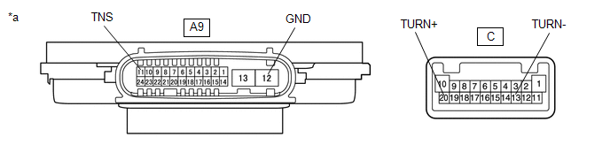
(a) Remove the headlight ECU sub-assembly RH.

Click here

(b) Measure the resistance according to the value(s) in the table below.

Standard Resistance:

Tester Connection

Condition

Specified Condition

C-20 (TURN+) - A9-11 (TNS)

Always

Below 1 Ω

C-13 (TURN-) - A9-12 (GND)

Always

Below 1 Ω

NG

REPLACE HEADLIGHT ECU SUB-ASSEMBLY RH

OK

21.

CHECK HEADLIGHT ASSEMBLY RH

(a) Connect the G15 combination meter assembly connector.

(b) Remove each headlight ECU sub-assembly, interchange the headlight assembly RH with LH and connect the connectors.

Click here

(c) Check that the front turn signal light operates normally.

OK:

Front turn signal light blinks.

(d) Connect the G15 combination meter assembly connector.

OK

REPLACE HEADLIGHT ASSEMBLY RH

NG

REPLACE COMBINATION METER ASSEMBLY

22.

CHECK HARNESS AND CONNECTOR (HEADLIGHT ASSEMBLY RH - COMBINATION METER ASSEMBLY AND BODY GROUND)

(a) Disconnect the A44 headlight assembly RH connector.

(b) Disconnect the G15 combination meter assembly connector.

(c) Measure the resistance according to the value(s) in the table below.

Standard Resistance:

Tester Connection

Condition

Specified Condition

A44-2 (B) - G15-7 (LR)

Always

Below 1 Ω

A44-7 (E) - Body ground

Always

Below 1 Ω

NG

REPAIR OR REPLACE HARNESS OR CONNECTOR

OK

23.

CHECK HEADLIGHT ASSEMBLY RH

(a) Connect the G15 combination meter assembly connector.

(b) Interchange the headlight assembly RH with LH and connect the connectors.

Click here

(c) Check that the front turn signal light operates normally.

OK:

Front turn signal light blinks.

OK

REPLACE HEADLIGHT ASSEMBLY RH

NG

REPLACE COMBINATION METER ASSEMBLY

24.

CONFIRM MODEL

(a) Choose the model to be inspected.

Result

Proceed to

w/ Cornering Light

A

w/o Cornering Light

B

B

GO TO STEP 31

A

25.

CHECK HARNESS AND CONNECTOR (REAR COMBINATION LIGHT ASSEMBLY RH - COMBINATION METER ASSEMBLY AND BODY GROUND)

(a) Disconnect the P9 rear combination light assembly RH connector.

(b) Disconnect the G15 combination meter assembly connector.

(c) Measure the resistance according to the value(s) in the table below.

Standard Resistance:

Tester Connection

Condition

Specified Condition

P9-3 (TRN) - G15-13 (TRNR)

Always

Below 1 Ω

P9-4 (E) - Body ground

Always

Below 1 Ω

NG

REPAIR OR REPLACE HARNESS OR CONNECTOR

OK

26.

CHECK REAR COMBINATION LIGHT SOCKET AND WIRE RH

(a) Connect the G15 combination meter assembly connector.

(b) Interchange the rear combination light socket and wire RH with LH and connect the connectors.

Click here

(c) Check that the rear turn signal light operates normally.

OK:

Rear turn signal light blinks.

OK

REPLACE REAR COMBINATION LIGHT SOCKET AND WIRE RH

NG

27.

INSPECT REAR COMBINATION LIGHT ASSEMBLY RH

(a) Remove the rear combination light assembly RH.

Click here

(b) Inspect the rear combination light assembly RH.

Click here

NG

REPLACE REAR COMBINATION LIGHT ASSEMBLY RH

OK

28.

CHECK HARNESS AND CONNECTOR (REAR LIGHT ASSEMBLY RH - COMBINATION METER ASSEMBLY AND BODY GROUND)

(a) Disconnect the P11 rear light assembly RH connector.

(b) Disconnect the G15 combination meter assembly connector.

(c) Measure the resistance according to the value(s) in the table below.

Standard Resistance:

Tester Connection

Condition

Specified Condition

P11-3 (B) - G15-13 (TRNR)

Always

Below 1 Ω

P11-4 (E) - Body ground

Always

Below 1 Ω

NG

REPAIR OR REPLACE HARNESS OR CONNECTOR

OK

29.

CHECK REAR LIGHT CORD RH

(a) Connect the G15 combination meter assembly connector.

(b) Interchange the rear light cord RH with LH and connect the connectors.

Click here

(c) Check that the rear turn signal light operates normally.

OK:

Rear turn signal light blinks.

OK

REPLACE REAR LIGHT CORD RH

NG

30.

INSPECT REAR LIGHT ASSEMBLY RH

(a) Remove the rear light assembly RH.

Click here

(b) Inspect the rear light assembly RH.

Click here

OK

REPLACE COMBINATION METER ASSEMBLY

NG

REPLACE REAR LIGHT ASSEMBLY RH

31.

CHECK HARNESS AND CONNECTOR (REAR COMBINATION LIGHT ASSEMBLY RH - COMBINATION METER ASSEMBLY AND BODY GROUND)

(a) Disconnect the P9 rear combination light assembly RH connector.

(b) Disconnect the G15 combination meter assembly connector.

(c) Measure the resistance according to the value(s) in the table below.

Standard Resistance:

Tester Connection

Condition

Specified Condition

P9-3 (TRN) - G15-13 (TRNR)

Always

Below 1 Ω

P9-4 (E) - Body ground

Always

Below 1 Ω

NG

REPAIR OR REPLACE HARNESS OR CONNECTOR

OK

32.

CHECK REAR COMBINATION LIGHT SOCKET AND WIRE RH

(a) Connect the G15 combination meter assembly connector.

(b) Interchange the rear combination light socket and wire RH with LH and connect the connectors.

Click here

(c) Check that the rear turn signal light operates normally.

OK:

Rear turn signal light blinks.

OK

REPLACE REAR COMBINATION LIGHT SOCKET AND WIRE RH

NG

33.

INSPECT REAR COMBINATION LIGHT ASSEMBLY RH

(a) Remove the rear combination light assembly RH.

Click here

(b) Inspect the rear combination light assembly RH.

Click here

OK

REPLACE COMBINATION METER ASSEMBLY

NG

REPLACE REAR COMBINATION LIGHT ASSEMBLY RH

    Fuel Sender Circuit Open (B150013)

    Turn Signal/Hazard Flasher Circuit Current Above Threshold (B150819)

    See More:

    Toyota Avalon (XX50) 2019-2022 Service & Repair Manual > Brake Fluid(for Hv Model): On-vehicle Inspection
    ON-VEHICLE INSPECTION CAUTION / NOTICE / HINT NOTICE: If using a dropper to adjust the fluid amount, make sure that the dropper has not been used with mineral oils, water or deteriorated brake fluid. Sealed areas may deteriorate and lead to fluid leaks, or the fluid may deteriorate and lead to decre ...

    Toyota Avalon (XX50) 2019-2022 Owners Manual

    Toyota Avalon (XX50) 2019-2022 Service & Repair Manual

    © 2024 Copyright www.tavalon.net
    0.0185