DESCRIPTION This DTC is set when the DCM (Telematics Transceiver) detects a malfunction in the telephone microphone assembly circuit. |
DTC No. | Detection Item |
DTC Detection Condition | Trouble Area | |
B1572 | Telephone Microphone Error |
Current of MCVD reaches malfunction criteria for 10 seconds while engine switch is on (IG). |
- Wire harness or connector
- Telephone microphone assembly
- Roof console box sub-assembly
- DCM (Telematics Transceiver)
| WIRING DIAGRAM w/o Sliding Roof
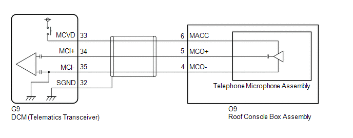 w/ Sliding Roof w/ Sliding Roof
 CAUTION / NOTICE / HINT
HINT: Before
performing this diagnostic procedure, make sure to perform Health Check
and confirm that the DCM/VIN registration information is correct. Click here
 PROCEDURE
(a) Choose the model to be inspected.
| Result |
Proceed to | | w/ Sliding Roof |
A | | w/o Sliding Roof |
B |
| B |
 | GO TO STEP 8 |
|
A |
 | |
(a) Turn the engine switch off.
(b) Connect the Techstream to the DLC3. (c) Turn the engine switch on (IG) and wait for 10 seconds.
(d) Turn the Techstream on. (e) Clear the DTCs. Body Electrical > Telematics > Clear DTCs
(f) Recheck for DTCs. Body Electrical > Telematics > Trouble Codes
|
Result | Proceed to | |
DTC B1572 is output | A | |
DTC B1572 is not output |
B |
| B |
| CHECK FOR INTERMITTENT PROBLEMS |
|
A | |
| |
| 3. |
INSPECT ROOF CONSOLE BOX SUB-ASSEMBLY (TELEPHONE MICROPHONE ASSEMBLY POWER SOURCE) |
| (a) Remove the roof console box sub-assembly but do not disconnect the connectors.
Click here |
 |
|
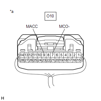
*a | Component with harness connected
(Roof Console Box Sub-assembly) | | |
(b) Measure the voltage and resistance according to the value(s) in the table below.
Standard Voltage: |
Tester Connection | Condition |
Specified Condition | |
O10-9 (MACC) - Body ground |
Engine switch on (ACC) |
4 to 6 V | Standard Resistance: |
Tester Connection | Condition |
Specified Condition | |
O10-7 (MCO-) - Body ground |
Always | Below 1 Ω |
| NG |
| GO TO STEP 6 |
|
OK | |
| |
| 4. |
CHECK HARNESS AND CONNECTOR (DCM (TELEMATICS TRANSCEIVER) - ROOF CONSOLE BOX ASSEMBLY) |
(a) Disconnect the G9 DCM (Telematics Transceiver) connector. (b) Disconnect the O10 roof console box sub-assembly connector.
(c) Measure the resistance according to the value(s) in the table below.
Standard Resistance: |
Tester Connection | Condition |
Specified Condition | |
G9-34 (MCI+) - O10-8 (MCO+) |
Always | Below 1 Ω | |
G9-34 (MCI+) or O10-8 (MCO+) - Body ground |
Always | 10 kΩ or higher | |
G9-35 (MCI-) - O10-7 (MCO-) |
Always | Below 1 Ω | |
G9-35 (MCI-) or O10-7 (MCO-) - Body ground |
Always | 10 kΩ or higher | |
G9-32 (SGND) - Body ground |
Always | 10 kΩ or higher |
| NG |
| REPAIR OR REPLACE HARNESS OR CONNECTOR |
|
OK | |
| |
| 5. |
REPLACE TELEPHONE MICROPHONE ASSEMBLY |
(a) Replace the telephone microphone assembly with a normal one and check if the same problem occurs again.
Click here OK: The system returns to normal.
| OK |
| END |
| NG |
| REPLACE ROOF CONSOLE BOX SUB-ASSEMBLY |
| 6. |
INSPECT DCM (TELEMATICS TRANSCEIVER) (TELEPHONE MICROPHONE ASSEMBLY POWER SOURCE) |
| (a) Remove the DCM (Telematics Transceiver) but do not disconnect the connectors.
Click here |
 |
|
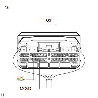
*a | Component with harness connected
(DCM (Telematics Transceiver)) | | |
(b) Measure the voltage and resistance according to the value(s) in the table below.
Standard Voltage: |
Tester Connection | Condition |
Specified Condition | |
G9-33 (MCVD) - Body ground |
Engine switch on (ACC) |
4 to 6 V | Standard Resistance: |
Tester Connection | Condition |
Specified Condition | |
G9-35 (MCI-) - Body ground |
Always | Below 1 Ω |
| OK |
| REPAIR OR REPLACE HARNESS OR CONNECTOR |
|
NG | |
| |
| 7. |
REPLACE DCM (TELEMATICS TRANSCEIVER) | (a) Replace the DCM (Telematics Transceiver).
Click here
NOTICE:
- The engine switch must be off.
- Do not swap the DCM (Telematics Transceiver) with one from another vehicle.
| NEXT |
| PERFORM DCM ACTIVATION |
(a) Turn the engine switch off.
(b) Connect the Techstream to the DLC3. (c) Turn the engine switch on (IG) and wait for 10 seconds.
(d) Turn the Techstream on. (e) Clear the DTCs. Body Electrical > Telematics > Clear DTCs
(f) Recheck for DTCs. Body Electrical > Telematics > Trouble Codes
|
Result | Proceed to | |
DTC B1572 is output | A | |
DTC B1572 is not output |
B |
| B |
| CHECK FOR INTERMITTENT PROBLEMS |
|
A | |
| |
| 9. |
INSPECT ROOF CONSOLE BOX SUB-ASSEMBLY (TELEPHONE MICROPHONE ASSEMBLY POWER SOURCE) |
| (a) Remove the roof console box sub-assembly but do not disconnect the connectors.
Click here |
 |
|
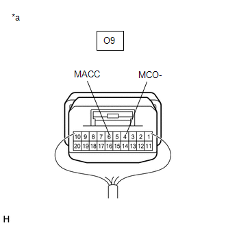
*a | Component with harness connected
(Roof Console Box Sub-assembly) | | |
(b) Measure the voltage and resistance according to the value(s) in the table below.
Standard Voltage: |
Tester Connection | Condition |
Specified Condition | |
O9-6 (MACC) - Body ground |
Engine switch on (ACC) |
4 to 6 V | Standard Resistance: |
Tester Connection | Condition |
Specified Condition | |
O9-4 (MCO-) - Body ground |
Always | Below 1 Ω |
| NG |
| GO TO STEP 12 |
|
OK | |
| |
| 10. |
CHECK HARNESS AND CONNECTOR (DCM (TELEMATICS TRANSCEIVER) - ROOF CONSOLE BOX ASSEMBLY) |
(a) Disconnect the G9 DCM (Telematics Transceiver) connector. (b) Disconnect the O9 roof console box sub-assembly connector.
(c) Measure the resistance according to the value(s) in the table below.
Standard Resistance: |
Tester Connection | Condition |
Specified Condition | |
G9-34 (MCI+) - O9-5 (MCO+) |
Always | Below 1 Ω | |
G9-34 (MCI+) or O9-5 (MCO+) - Body ground |
Always | 10 kΩ or higher | |
G9-35 (MCI-) - O9-4 (MCO-) |
Always | Below 1 Ω | |
G9-35 (MCI-) or O9-4 (MCO-) - Body ground |
Always | 10 kΩ or higher | |
G9-32 (SGND) - Body ground |
Always | 10 kΩ or higher |
| NG |
| REPAIR OR REPLACE HARNESS OR CONNECTOR |
|
OK | |
| |
| 11. |
REPLACE TELEPHONE MICROPHONE ASSEMBLY |
(a) Replace the telephone microphone assembly with a normal one and check if the same problem occurs again.
Click here OK: The system returns to normal.
| OK |
| END |
| NG |
| REPLACE ROOF CONSOLE BOX SUB-ASSEMBLY |
| 12. |
INSPECT DCM (TELEMATICS TRANSCEIVER) (TELEPHONE MICROPHONE ASSEMBLY POWER SOURCE) |
| (a) Remove the DCM (Telematics Transceiver) but do not disconnect the connectors.
Click here | |
|
|
*a | Component with harness connected
(DCM (Telematics Transceiver)) | | |
(b) Measure the voltage and resistance according to the value(s) in the table below.
Standard Voltage: |
Tester Connection | Condition |
Specified Condition | |
G9-33 (MCVD) - Body ground |
Engine switch on (ACC) |
4 to 6 V | Standard Resistance: |
Tester Connection | Condition |
Specified Condition | |
G9-35 (MCI-) - Body ground |
Always | Below 1 Ω |
| OK |
| REPAIR OR REPLACE HARNESS OR CONNECTOR |
|
NG | |
| |
| 13. |
REPLACE DCM (TELEMATICS TRANSCEIVER) | (a) Replace the DCM (Telematics Transceiver).
Click here
NOTICE:
- The engine switch must be off.
- Do not swap the DCM (Telematics Transceiver) with one from another vehicle.
| NEXT |
| PERFORM DCM ACTIVATION | | 

