|
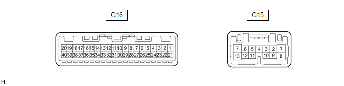
Terminal No. (Symbol) | Wiring Color |
Terminal Description | Signal Input/Output |
Condition | Specified Condition |
|
G16-1 (ILL-) - Body ground |
LA-L - Body ground | Illumination signal |
Output | Taillights off → Taillights on |
Below 1 V → Pulse generation |
|
G16-2 (EP) - Body ground |
W-B - Body ground | Ground |
- | Always |
Below 1 Ω |
|
G16-4 (INT) - Body ground |
L - Body ground | Tire pressure warning ECU and receiver signal |
Output |
- Power switch on (IG)
- Steering pad switch assembly operated, "TPWS" selected on the
multi-information display and "OK" switch (steering pad switch assembly)
pressed and held → "OK" switch (steering pad switch assembly) off
| Below 1.5 V → 8 to 15 V |
|
G16-5 (SI) - Body ground |
W - Body ground | Speed signal for other systems (Input) |
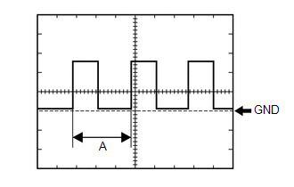
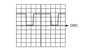
Input | Power switch on (IG), wheel being rotated |
Pulse generation (See waveform 1) |
|
G16-6 (+S) - Body ground |
L - Body ground | Speed signal for other systems (Output) |
Output | Power switch on (IG), wheel being rotated |
Pulse generation (See waveform 1) |
|
G16-8 (IND) - Body ground |
B - Body ground | Vehicle proximity notification system warning signal |
Input | Approximately 3 seconds after turning power switch on (IG) |
Below 1 V |
|
G16-14 (FR) - G16-33 (FE) |
LG - BE | Fuel level signal |
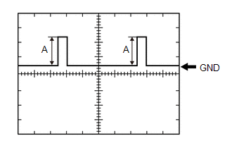
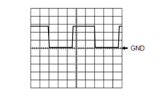
Input | Power switch on (IG), fuel level full → Fuel level low (fuel level warning light on) |
Pulse generation (See waveform 2) |
|
G16-15 (FV) - Body ground |
GR - Body ground | Fuel sender gauge (Power source) |
- | Power switch on (IG) |
Pulse generation (See waveform 3) |
|
G16-17 (WLVL) - Body ground |
LG - Body ground | Washer fluid level signal |
Input | Power switch on (IG), washer fluid level not low → Washer fluid level low |
11 to 14 V → Below 1 V |
|
G16-18 (RLMT) -Body ground |
BE - Body ground | Rear seat belt warning light LH signal |
Output | Power
switch on (IG), rear seat belt warning light LH (radio and display
receiver assembly) off → Rear seat belt warning light LH (radio and
display receiver assembly) on | 11 to 14 V → Below 1 V |
|
G16-19 (RCMT) -Body ground |
R - Body ground | Rear seat belt warning light center signal |
Output | Power
switch on (IG), rear seat belt warning light center (radio and display
receiver assembly) off → Rear seat belt warning light center (radio and
display receiver assembly) on | 11 to 14 V → Below 1 V |
|
G16-20 (RRMT) -Body ground |
G - Body ground | Rear seat belt warning light RH signal |
Output | Power
switch on (IG), rear seat belt warning light RH (radio and display
receiver assembly) off → Rear seat belt warning light RH (radio and
display receiver assembly) on | 11 to 14 V → Below 1 V |
|
G16-21 (ES) - Body ground |
W-B - Body ground | Ground |
- | Always |
Below 1 Ω |
|
G16-24 (RLSB) - Body ground |
SB - Body ground | Rear seat belt buckle switch LH signal |
Input | Power switch on (IG), rear seat belt LH unfastened → Fastened |
Below 1 V → 11 to 14 V |
|
G16-25 (RCSB) - Body ground |
B - Body ground | Rear seat belt buckle switch center signal |
Input | Power switch on (IG), rear seat belt center unfastened → Fastened |
Below 1 V → 11 to 14 V |
|
G16-26 (RRSB) - Body ground |
LG - Body ground | Rear seat belt buckle switch RH signal |
Input | Power switch on (IG), rear seat belt RH unfastened → Fastened |
Below 1 V → 11 to 14 V |
|
G16-27 (OILW) - Body ground |
W - Body ground | Engine oil level signal |
Input | Power switch on (IG), engine oil level not low → Engine oil level low |
Below 1 V → 11 to 14 V |
|
G16-28 (MSM+) - Body ground |
GR - Body ground | Steering pad switch assembly signal |
Input | Power switch on (IG), up, down, right and left switches on steering pad switch assembly not pushed |
4.8 to 5.2 V |
|
G16-29 (MSTI) - Body ground |
R - Body ground | Steering pad switch assembly signal |
Input | Power switch on (IG), OK and back switches on steering pad switch assembly not pushed |
4.8 to 5.2 V |
|
G16-31 (CANL) | W |
CAN communication line |
Input/Output | - |
- |
| G16-32 (CANH) |
B | CAN communication line |
Input/Output | - |
- |
|
G16-34 (LST1) - Body ground |
L - Body ground |
Fuel lid operation signal |
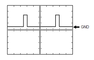
Input | "Ready to Refuel" displayed on multi-information display |
Pulse generation (See waveform 4) |
|
"Close Fuel Lid" displayed on multi-information display |
Pulse generation (See waveform 5) |
|
Power switch on (IG) |
11 to 14 V |
|
G16-36 (TX+) | G |
Local bus communication line |
Input/Output | - |
- |
| G16-37 (TX-) |
W | Local bus communication line |
Input/Output | - |
- |
| G16-39 (IG+) - Body ground |
GR - Body ground | Power switch signal |
- | Power switch off → Power switch on (IG) |
Below 1 V → 11 to 14 V |
|
G16-40 (B) - Body ground |
LA-B - Body ground | Auxiliary battery |
- | Power switch off |
11 to 14 V |
|
G15-1 (ODO) - Body ground |
LA-L - Body ground | ODO/TRIP switch signal |
Input | Power switch on (IG), ODO/TRIP switch (trip switch) not pushed |
4.8 to 5.2 V |
|
G15-2 (TR) - Body ground |
L - Body ground | Light control rheostat switch signal |
Input | Power
switch on (IG), light control rheostat up switch (trip switch) and
light control rheostat down switch (trip switch) not pushed |
4.8 to 5.2 V |
|
G15-3 (HAZ) - Body ground |
LA-R - Body ground | Hazard warning switch signal |
Input | Hazard
warning switch assembly (radio and display receiver assembly) off →
Hazard warning switch assembly (radio and display receiver assembly)
pushed | 11 to 14 V → Below 1 V |
|
G15-5 (SW3) - Body ground |
LA-B - Body ground | Ground for trip switch |
- | Always |
Below 1 Ω |
|
G15-7 (LR) - Body ground |
LA-G - Body ground | Front turn signal light RH signal |
Output | Power switch on (IG), RH turn indicator light off → RH turn indicator light blinking |
Below 1 V → 11 to 14 V ←→ Below 1 V |
|
G15-8 (B) - Body ground |
LA-B - Body ground | Auxiliary battery |
- | Power switch off |
11 to 14 V |
|
G15-10 (TRNL) - Body ground |
BE - Body ground | Rear turn signal light LH signal |
Output | Power switch on (IG), LH turn indicator light off → LH turn indicator light blinking |
Below 1 V → 11 to 14 V ←→ Below 1 V |
|
G15-11 (LL) - Body ground |
LA-LG - Body ground | Front turn signal light LH signal |
Output | Power switch on (IG), LH turn indicator light off → LH turn indicator light blinking |
Below 1 V → 11 to 14 V ←→ Below 1 V |
|
G15-13 (TRNR) - Body ground |
BE - Body ground | Rear turn signal light RH signal |
Output | Power switch on (IG), RH turn indicator light off → RH turn indicator light blinking |
Below 1 V → 11 to 14 V ←→ Below 1 V |