Toyota Avalon (XX50) 2019-2022 Service & Repair Manual: Dcm Power Source Circuit

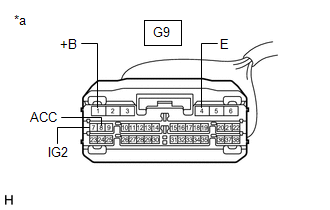
DESCRIPTION

This is the power source circuit to operate the DCM (Telematics Transceiver).

WIRING DIAGRAM

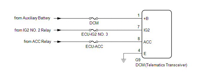
CAUTION / NOTICE / HINT

NOTICE:

Inspect the fuses for circuits related to this system before performing the following procedure.

PROCEDURE

1.

CHECK HARNESS AND CONNECTOR (DCM (TELEMATICS TRANSCEIVER) - AUXILIARY BATTERY AND GROUND)

(a) Disconnect the G9 DCM (Telematics Transceiver) connector.

*a

Front view of wire harness connector

(to DCM (Telematics Transceiver))

(b) Measure the resistance according to the value(s) in the table below.

Standard Resistance:

Tester Connection

Condition

Specified Condition

G9-4 (E) - Body ground

Always

Below 1 Ω

(c) Measure the voltage according to the value(s) in the table below.

Standard Voltage:

Tester Connection

Condition

Specified Condition

G9-1 (+B) - G9-4 (E)

Always

11 to 14 V

G9-7 (IG2) - G9-4 (E)

Power switch on (IG)

11 to 14 V

G9-8 (ACC) - G9-4 (E)

Power switch on (ACC)

11 to 14 V

OK

PROCEED TO NEXT SUSPECTED AREA SHOWN IN PROBLEM SYMPTOMS TABLE

NG

REPAIR OR REPLACE HARNESS OR CONNECTOR

    Dcm Operation History

    Diagnosis System

    See More:

    Toyota Avalon (XX50) 2019-2022 Service & Repair Manual > Panoramic View Monitor System(for Hv Model): System Diagram
    SYSTEM DIAGRAM Sender Receiver Signal Line Steering Sensor Parking Assist ECU Data continuity flag Steering angle signal CAN Skid Control ECU Parking Assist ECU Wheel speed signal Vehicle speed signal CAN Main Body ECU (Multiplex Network Body ECU) Parking Assist ECU Courtesy light switch signal Oute ...

    Toyota Avalon (XX50) 2019-2022 Owners Manual

    Toyota Avalon (XX50) 2019-2022 Service & Repair Manual

    © 2024 Copyright www.tavalon.net
    0.0154