DESCRIPTION The side collision sensor RH circuit (bus 2) consists of the airbag ECU assembly and side No. 1 airbag sensor RH. The side No. 1 airbag sensor RH detects impacts to the vehicle and sends signals to the airbag ECU assembly to determine if the airbags and pretensioners should be deployed. These DTCs are stored when a malfunction is detected in the side collision sensor RH circuit (bus 2).
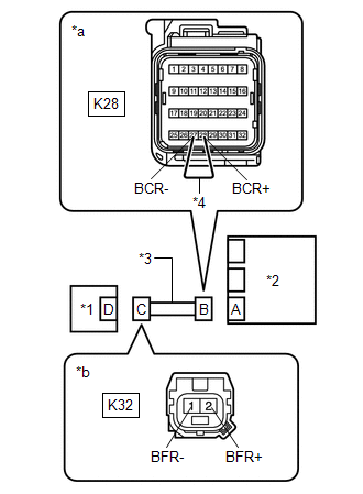
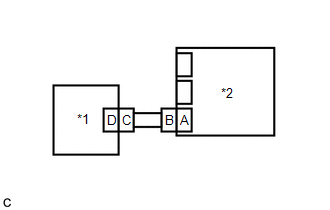
WIRING DIAGRAM 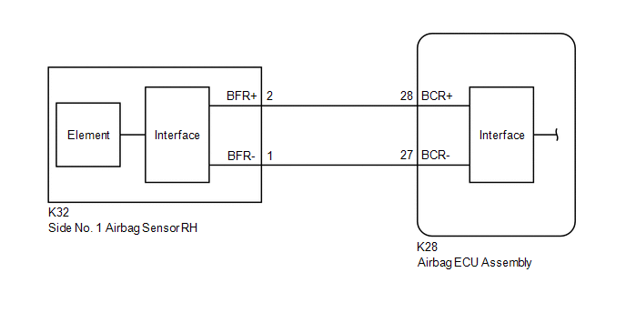 CAUTION / NOTICE / HINT NOTICE: After turning the engine switch off, waiting time may be required before disconnecting the cable from the negative (-) battery terminal. Therefore, make sure to read the disconnecting the cable from the negative (-) battery terminal notices before proceeding with work. Click here
PROCEDURE
(a) Turn the engine switch off. (b) Disconnect the cable from the negative (-) battery terminal. CAUTION: Wait at least 90 seconds after disconnecting the cable from the negative (-) battery terminal to disable the SRS system. (c) Check that the connectors are properly connected to the airbag ECU assembly and side No. 1 airbag sensor RH. OK: The connectors are properly connected.
(a) Disconnect the connectors from the airbag ECU assembly and side No. 1 airbag sensor RH. (b) Check that the terminals of the connectors are not deformed or damaged. OK: The terminals are not deformed or damaged.
(b) Turn the engine switch on (IG). (c) Measure the voltage according to the value(s) in the table below. Standard Voltage:
(d) Turn the engine switch off. (e) Disconnect the cable from the negative (-) battery terminal. CAUTION: Wait at least 90 seconds after disconnecting the cable from the negative (-) battery terminal to disable the SRS system. (f) Using a service wire, connect terminals 28 (BCR+) and 27 (BCR-) of connector B. NOTICE: Do not forcibly insert the service wire into the terminals of the connector when connecting the wire. (g) Measure the resistance according to the value(s) in the table below. Standard Resistance:
(h) Disconnect the service wire from connector B. (i) Measure the resistance according to the value(s) in the table below. Standard Resistance:
(b) Interchange the side No. 1 airbag sensor RH with LH and connect the connectors. (c) Connect the cable to the negative (-) battery terminal. (d) Turn the engine switch on (IG), and wait for at least 60 seconds. (e) Clear the DTCs stored in memory. Body Electrical > SRS Airbag > Clear DTCs(f) Turn the engine switch off. (g) Turn the engine switch on (IG), and wait for at least 60 seconds. (h) Check for DTCs. Body Electrical > SRS Airbag > Trouble CodesHINT: Codes other than DTCs B162B, B162C, B163B and B163C may be output at this time, but they are not related to this check.
(i) Turn the engine switch off. (j) Disconnect the cable from the negative (-) battery terminal. CAUTION: Wait at least 90 seconds after disconnecting the cable from the negative (-) battery terminal to disable the SRS system. (k) Return the side No. 1 airbag sensor RH and LH to their original positions and connect the connectors.
|
Toyota Avalon (XX50) 2019-2022 Service & Repair Manual > Electronically Controlled Brake System(for Hv Model): IG1 Voltage Supply too High (C1417,C14DF)
DESCRIPTION If a malfunction is detected in the power source circuit, the skid control ECU (brake booster with master cylinder assembly) stores DTC C1417 and prohibits operation of ABS, brake assist, regenerative brake cooperative control, etc. DTC C1417 is stored if an excessive ECU voltage due to ...