DESCRIPTION The seat position airbag sensor circuit consists of the airbag ECU assembly and seat position airbag sensor. DTC B1653 is stored when a malfunction is detected in the seat position airbag sensor circuit.
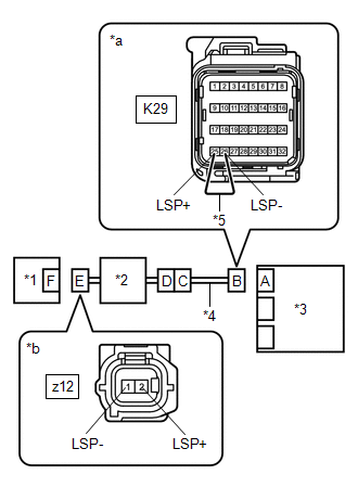
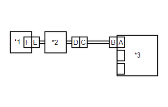
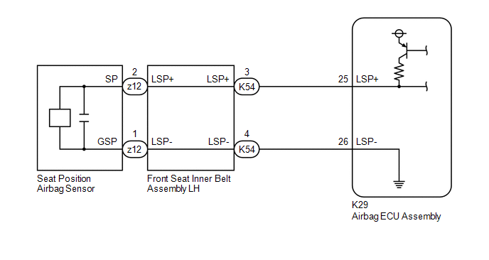
WIRING DIAGRAM w/o Seat Position Memory System: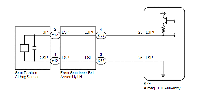 w/ Seat Position Memory System: w/ Seat Position Memory System:
 CAUTION / NOTICE / HINT NOTICE: After turning the engine switch off, waiting time may be required before disconnecting the cable from the negative (-) battery terminal. Therefore, make sure to read the disconnecting the cable from the negative (-) battery terminal notices before proceeding with work. Click here
PROCEDURE
(a) Turn the engine switch off. (b) Disconnect the cable from the negative (-) battery terminal. CAUTION: Wait at least 90 seconds after disconnecting the cable from the negative (-) battery terminal to disable the SRS system. (c) Check that the connectors are properly connected to the airbag ECU assembly, front seat inner belt assembly LH and seat position airbag sensor. OK: The connectors are properly connected.
(a) Disconnect the connectors from the airbag ECU assembly, front seat inner belt assembly LH and seat position airbag sensor. (b) Check that the terminals of the connectors are not deformed or damaged. OK: The terminals are not deformed or damaged.
(b) Connect the cable to the negative (-) battery terminal. (c) Turn the engine switch on (IG). (d) Measure the voltage according to the value(s) in the table below. Standard Voltage:
(e) Turn the engine switch off. (f) Disconnect the cable from the negative (-) battery terminal. CAUTION: Wait at least 90 seconds after disconnecting the cable from the negative (-) battery terminal to disable the SRS system. (g) Using a service wire, connect terminals 25 (LSP+) and 26 (LSP-) of connector B. NOTICE: Do not forcibly insert the service wire into the terminals of the connector when connecting the wire. (h) Measure the resistance according to the value(s) in the table below. Standard Resistance:
(i) Disconnect the service wire from connector B. (j) Measure the resistance according to the value(s) in the table below. Standard Resistance:
(b) Connect the cable to the negative (-) battery terminal. (c) Turn the engine switch on (IG), and wait for at least 60 seconds. (d) Clear the DTCs stored in memory. Body Electrical > SRS Airbag > Clear DTCs(e) Turn the engine switch off. (f) Turn the engine switch on (IG), and wait for at least 60 seconds. (g) Check for DTCs. Body Electrical > SRS Airbag > Trouble CodesOK: DTC B1653 is not output. HINT: Codes other than DTC B1653 may be output at this time, but they are not related to this check.
(b) Disconnect the cable from the negative (-) battery terminal. CAUTION: Wait at least 90 seconds after disconnecting the cable from the negative (-) battery terminal to disable the SRS system. (c) Replace the seat position airbag sensor with a known good one. Click here
HINT: Perform the following inspection using known good parts from another vehicle if possible. (d) Connect the cable to the negative (-) battery terminal. (e) Turn the engine switch on (IG), and wait for at least 60 seconds. (f) Clear the DTCs stored in memory. Body Electrical > SRS Airbag > Clear DTCs(g) Turn the engine switch off. (h) Turn the engine switch on (IG), and wait for at least 60 seconds. (i) Check for DTCs. Body Electrical > SRS Airbag > Trouble CodesOK: DTC B1653 is not output. HINT: Codes other than DTC B1653 may be output at this time, but they are not related to this check. (j) Turn the engine switch off. (k) Disconnect the cable from the negative (-) battery terminal. CAUTION: Wait at least 90 seconds after disconnecting the cable from the negative (-) battery terminal to disable the SRS system. (l) Restore the seat position airbag sensor that was installed for testing to its original location. Click here
(a) Disconnect the floor wire connector from the front seat inner belt assembly LH. 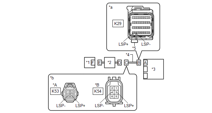
(b) Connect the cable to the negative (-) battery terminal. (c) Turn the engine switch on (IG). (d) Measure the voltage according to the value(s) in the table below. Standard Voltage: w/o Seat Position Memory System:
(e) Turn the engine switch off. (f) Disconnect the cable from the negative (-) battery terminal. CAUTION: Wait at least 90 seconds after disconnecting the cable from the negative (-) battery terminal to disable the SRS system. (g) Using a service wire, connect terminals 25 (LSP+) and 26 (LSP-) of connector B. NOTICE: Do not forcibly insert the service wire into the terminals of the connector when connecting the wire. (h) Measure the resistance according to the value(s) in the table below. Standard Resistance: w/o Seat Position Memory System:
(i) Disconnect the service wire from connector B. (j) Measure the resistance according to the value(s) in the table below. Standard Resistance: w/o Seat Position Memory System:
|
Toyota Avalon (XX50) 2019-2022 Service & Repair Manual > Lighting System(for Hv Model Without Cornering Light): Terminals Of Ecu
TERMINALS OF ECU CHECK MAIN BODY ECU (MULTIPLEX NETWORK BODY ECU) AND INSTRUMENT PANEL JUNCTION BLOCK ASSEMBLY (a) Disconnect the instrument panel junction block assembly and main body ECU (multiplex network body ECU) connectors. (b) Measure the voltage and resistance according to the value(s) in th ...