DESCRIPTION The passenger airbag ON/OFF indicator circuit consists of the airbag ECU assembly and passenger airbag ON/OFF indicator (radio and display receiver assembly). The passenger airbag ON/OFF indicator indicates the operation condition of the instrument panel passenger airbag assembly and lower No. 2 instrument panel airbag assembly. DTC B1660 is stored when a malfunction is detected in the passenger airbag ON/OFF indicator circuit.
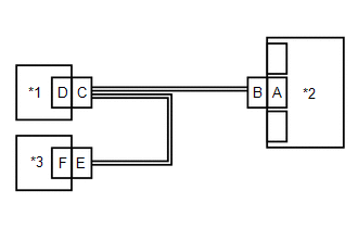
WIRING DIAGRAM 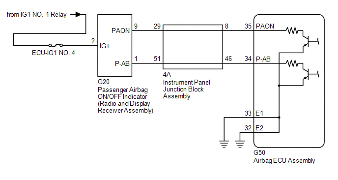 CAUTION / NOTICE / HINT NOTICE:
PROCEDURE
(a) Turn the engine switch on (IG). (b) Check the passenger airbag ON/OFF indicator operation. HINT: Refer to the normal condition of the passenger airbag ON/OFF indicator. Click here
(a) Turn the engine switch off. (b) Disconnect the cable from the negative (-) battery terminal. CAUTION: Wait at least 90 seconds after disconnecting the cable from the negative (-) battery terminal to disable the SRS system. (c) Check that the connectors are properly connected to the airbag ECU assembly, radio and display receiver assembly and instrument panel junction block assembly. OK: The connectors are properly connected.
(a) Disconnect the connectors from the airbag ECU assembly, radio and display receiver assembly and instrument panel junction block assembly. (b) Check that the terminals of the connectors are not deformed or damaged. OK: The terminals are not deformed or damaged.
(a) Connect the connector to the radio and display receiver assembly and instrument panel junction block assembly. (b) Connect the cable to the negative (-) battery terminal. (c) Turn the engine switch on (IG). (d) Check the passenger airbag ON/OFF indicator operation. OK: The passenger airbag ON/OFF indicator does not come on.
(b) Disconnect the cable from the negative (-) battery terminal. CAUTION: Wait at least 90 seconds after disconnecting the cable from the negative (-) battery terminal to disable the SRS system. (c) Connect the connector to the airbag ECU assembly. (d) Connect the cable to the negative (-) battery terminal. (e) Turn the engine switch on (IG), and wait for at least 60 seconds. (f) Clear the DTCs stored in memory. Body Electrical > SRS Airbag > Clear DTCs(g) Turn the engine switch off. (h) Turn the engine switch on (IG), and wait for at least 60 seconds. (i) Check for DTCs. Body Electrical > SRS Airbag > Trouble CodesOK: DTC B1660 is not output. HINT: Codes other than DTC B1660 may be output at this time, but they are not related to this check.
(b) Disconnect the cable from the negative (-) battery terminal. CAUTION: Wait at least 90 seconds after disconnecting the cable from the negative (-) battery terminal to disable the SRS system. (c) Disconnect the connector from the radio and display receiver assembly. (d) Connect the cable to the negative (-) battery terminal. (e) Turn the engine switch on (IG). (f) Measure the voltage according to the value(s) in the table below. Standard Voltage:
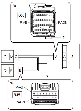
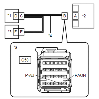
(g) Turn the engine switch off. (h) Disconnect the cable from the negative (-) battery terminal. CAUTION: Wait at least 90 seconds after disconnecting the cable from the negative (-) battery terminal to disable the SRS system. (i) Using a service wire, connect terminals 35 (PAON) and 34 (P-AB) of connector B. NOTICE: Do not forcibly insert the service wire into the terminals of the connector when connecting the wire. (j) Measure the resistance according to the value(s) in the table below. Standard Resistance:
(k) Disconnect the service wire from connector B. (l) Measure the resistance according to the value(s) in the table below. Standard Resistance:
(a) Disconnect the connector from the instrument panel junction block assembly. 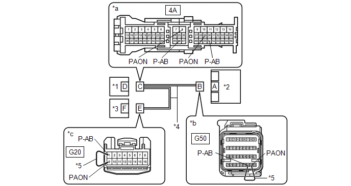
(b) Using a service wire, connect terminals 35 (PAON) and 34 (P-AB) of connector B. NOTICE: Do not forcibly insert the service wire into the terminals of the connector when connecting the wire. (c) Measure the resistance according to the value(s) in the table below. Standard Resistance:
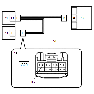
(d) Disconnect the service wire from connector B. (e) Using a service wire, connect terminals 9 (PAON) and 1 (P-AB) of connector E. NOTICE: Do not forcibly insert the service wire into the terminals of the connector when connecting the wire. (f) Measure the resistance according to the value(s) in the table below. Standard Resistance:
(g) Disconnect the service wire from connector E. (h) Measure the resistance according to the value(s) in the table below. Standard Resistance:
(a) Turn the engine switch off. (b) Disconnect the cable from the negative (-) battery terminal. CAUTION: Wait at least 90 seconds after disconnecting the cable from the negative (-) battery terminal to disable the SRS system. (c) Check that the connectors are properly connected to the airbag ECU assembly, radio and display receiver assembly and instrument panel junction block assembly. OK: The connectors are properly connected.
(a) Disconnect the connectors from the airbag ECU assembly, radio and display receiver assembly and instrument panel junction block assembly. (b) Check that the terminals of the connectors are not deformed or damaged. OK: The terminals are not deformed or damaged.
(b) Connect the cable to the negative (-) battery terminal. (c) Turn the engine switch on (IG). (d) Measure the voltage according to the value(s) in the table below. Standard Voltage:
(e) Turn the engine switch off. (f) Disconnect the cable from the negative (-) battery terminal. CAUTION: Wait at least 90 seconds after disconnecting the cable from the negative (-) battery terminal to disable the SRS system. (g) Using a service wire, connect terminals 35 (PAON) and 34 (P-AB) of connector B. NOTICE: Do not forcibly insert the service wire into the terminals of the connector when connecting the wire. (h) Measure the resistance according to the value(s) in the table below. Standard Resistance:
(i) Disconnect the service wire from connector B. (j) Measure the resistance according to the value(s) in the table below. Standard Resistance:
(b) Turn the engine switch on (IG). (c) Measure the voltage according to the value(s) in the table below. Standard Voltage:
(d) Turn the engine switch off. (e) Disconnect the cable from the negative (-) battery terminal. CAUTION: Wait at least 90 seconds after disconnecting the cable from the negative (-) battery terminal to disable the SRS system.
(b) Connect the cable to the negative (-) battery terminal. (c) Turn the engine switch on (IG). (d) Check the passenger airbag ON/OFF indicator according to the conditions in the table below. OK:
(e) Turn the engine switch off. (f) Disconnect the cable from the negative (-) battery terminal. CAUTION: Wait at least 90 seconds after disconnecting the cable from the negative (-) battery terminal to disable the SRS system.
(b) Connect the cable to the negative (-) battery terminal. (c) Turn the engine switch on (IG), and wait for at least 60 seconds. (d) Clear the DTCs stored in memory. Body Electrical > SRS Airbag > Clear DTCs(e) Turn the engine switch off. (f) Turn the engine switch on (IG), and wait for at least 60 seconds. (g) Check for DTCs. Body Electrical > SRS Airbag > Trouble CodesOK: DTC B1660 is not output. HINT: Codes other than DTC B1660 may be output at this time, but they are not related to this check.
(a) Disconnect the connector from the instrument panel junction block assembly.
(b) Using a service wire, connect terminals 35 (PAON) and 34 (P-AB) of connector B. NOTICE: Do not forcibly insert the service wire into the terminals of the connector when connecting the wire. (c) Measure the resistance according to the value(s) in the table below. Standard Resistance:
(d) Disconnect the service wire from connector B. (e) Using a service wire, connect terminals 9 (PAON) and 1 (P-AB) of connector E. NOTICE: Do not forcibly insert the service wire into the terminals of the connector when connecting the wire. (f) Measure the resistance according to the value(s) in the table below. Standard Resistance:
(g) Disconnect the service wire from connector E. (h) Measure the resistance according to the value(s) in the table below. Standard Resistance:
|
Toyota Avalon (XX50) 2019-2022 Service & Repair Manual > Heating / Air Conditioning: Humidity Sensor
ComponentsCOMPONENTS ILLUSTRATION *1 AIR CONDITIONING THERMISTOR ASSEMBLY *2 SENSOR COVER InstallationINSTALLATION PROCEDURE 1. INSTALL AIR CONDITIONING THERMISTOR ASSEMBLY (a) Temporarily install the air conditioning thermistor assembly to the windshield glass as shown in the illustration. *a Stop ...