REMOVAL CAUTION / NOTICE / HINT The necessary procedures (adjustment, calibration, initialization or registration) that must be performed after parts are removed and installed, or replaced during airbag ECU assembly removal/installation are shown below. Necessary Procedures After Parts Removed/Installed/Replaced (for Gasoline Model)
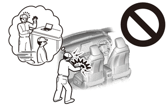
PROCEDURE 1. PRECAUTION CAUTION: Be sure to read Precaution thoroughly before servicing. for Gasoline Model: Click here for HV Model: Click here
 NOTICE: After turning the engine switch (for Gasoline Model) or power switch (for HV Model) off, waiting time may be required before disconnecting the cable from the negative (-) auxiliary battery terminal. Therefore, make sure to read the disconnecting the cable from the negative (-) auxiliary battery terminal notices before proceeding with work. Click here
2. REMOVE FRONT SEAT ASSEMBLY (a) Remove the front seat assembly LH and front seat assembly RH. Click here 3. REMOVE CONSOLE ASSEMBLY Click here 4. DISCONNECT REAR CENTER SEAT OUTER BELT ASSEMBLY (for Gasoline Model) Click here 5. REMOVE REAR SEAT CUSHION ASSEMBLY (for Gasoline Model) Click here 6. REMOVE REAR SEAT CUSHION LOCK HOOK (for Gasoline Model) Click here 7. REMOVE FRONT DOOR SCUFF PLATE LH Click here 8. REMOVE COWL SIDE TRIM SUB-ASSEMBLY LH Click here 9. DISCONNECT FRONT DOOR OPENING TRIM WEATHERSTRIP LH HINT: Disconnect the front door opening trim weatherstrip LH to the extent that allows the removal of the center pillar lower garnish LH. 10. REMOVE REAR DOOR SCUFF PLATE LH (for Gasoline Model) Click here 11. REMOVE REAR DOOR SCUFF PLATE LH (for HV Model) Click here 12. DISCONNECT REAR DOOR OPENING TRIM WEATHERSTRIP LH HINT: Disconnect the rear door opening trim weatherstrip LH to the extent that allows the removal of the center pillar lower garnish LH. 13. REMOVE CENTER PILLAR LOWER GARNISH LH Click here 14. REMOVE NO. 1 INSTRUMENT PANEL UNDER COVER SUB-ASSEMBLY Click here 15. REMOVE FRONT DOOR SCUFF PLATE RH HINT: Use the same procedure as for the LH side. Click here
16. REMOVE COWL SIDE TRIM SUB-ASSEMBLY RH HINT: Use the same procedure as for the LH side. Click here
17. DISCONNECT FRONT DOOR OPENING TRIM WEATHERSTRIP RH HINT: Disconnect the front door opening trim weatherstrip RH to the extent that allows the removal of the center pillar lower garnish RH. 18. REMOVE REAR DOOR SCUFF PLATE RH (for Gasoline Model) HINT: Use the same procedure as for the LH side. Click here
19. REMOVE REAR DOOR SCUFF PLATE RH (for HV Model) HINT: Use the same procedure as for the LH side. Click here
20. DISCONNECT REAR DOOR OPENING TRIM WEATHERSTRIP RH HINT: Disconnect the rear door opening trim weatherstrip RH to the extent that allows the removal of the center pillar lower garnish RH. 21. REMOVE CENTER PILLAR LOWER GARNISH RH HINT: Use the same procedure as for the LH side. Click here
22. REMOVE NO. 2 INSTRUMENT PANEL UNDER COVER SUB-ASSEMBLY Click here 23. REMOVE ACCELERATOR PEDAL PAD for 2GR-FKS: Click here for A25A-FXS: Click here
24. REMOVE ACCELERATOR PEDAL for 2GR-FKS: Click here
for A25A-FXS: Click here
25. DISCONNECT FRONT FLOOR CARPET ASSEMBLY
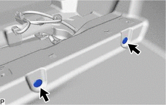
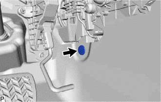
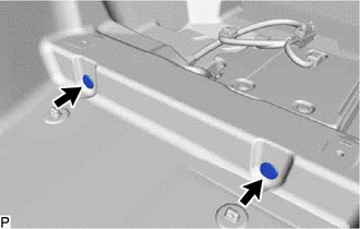
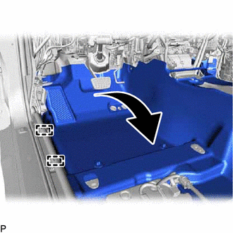
26. REMOVE NO. 1 CONSOLE BOX DUCT (a) Remove the clip. 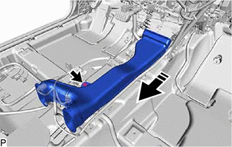
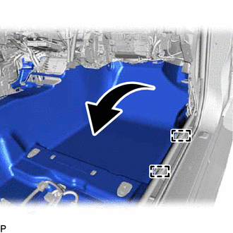
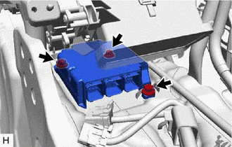
(b) Remove the No. 1 console box duct as shown in the illustration. 27. REMOVE AIRBAG ECU ASSEMBLY (a) Check that the engine switch (for Gasoline Model) or power switch (for HV Model) is off. (b) Check that the cable is disconnected from the negative (-) auxiliary battery terminal. CAUTION: Wait at least 90 seconds after disconnecting the cable from the negative (-) auxiliary battery terminal to disable the SRS system. 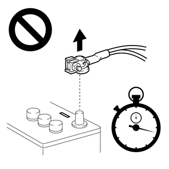 (c) Push down the part (A) in the direction indicated by the arrow (1) to release the lock, and then move the lock lever in the direction indicated by the arrow (2) shown in the illustration to disconnect the connectors. NOTICE: When disconnecting any airbag connector, take care not to damage the airbag wire harness. 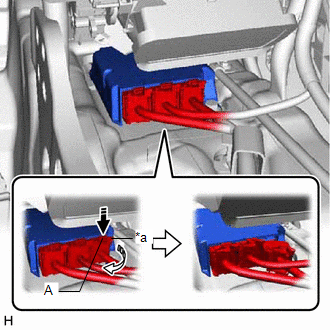
| |||||||||||||||||||||||||||||||||||||||||||||||||||||||||||||||||||||||||||||||||||||
Toyota Avalon (XX50) 2019-2022 Service & Repair Manual > Tire And Wheel System: How To Proceed With Troubleshooting
PROCEDURE 1. CHECK TIRE AND WHEEL SYSTEM DIAGNOSIS OF IRREGULAR TIRE WEAR GO TO STEP 11 DIAGNOSIS OF TIRE VIBRATION 2. TIGHTEN WHEEL NUTS Click here NEXT 3. INSPECT TIRES Click here NG GO TO STEP 10 OK 4. INSPECT AND/OR ADJUST WHEEL BALANCE Click here NEXT 5. INSPECT FRONT AXLE HUB BEARING LOOSENESS ...