REMOVAL CAUTION / NOTICE / HINT The necessary procedures (adjustment, calibration, initialization or registration) that must be performed after parts are removed and installed, or replaced during lower No. 2 instrument panel airbag assembly removal/installation are shown below. Necessary Procedures After Parts Removed/Installed/Replaced (for Gasoline Model)
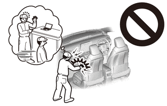
PROCEDURE 1. PRECAUTION CAUTION: Be sure to read Precaution thoroughly before servicing. for Gasoline Model: Click here for HV Model: Click here
 NOTICE: After turning the engine switch (for Gasoline Model) or power switch (for HV Model) off, waiting time may be required before disconnecting the cable from the negative (-) auxiliary battery terminal. Therefore, make sure to read the disconnecting the cable from the negative (-) auxiliary battery terminal notices before proceeding with work. Click here
2. REMOVE LUGGAGE TRIM SERVICE HOLE COVER (for HV Model) Click here 3. DISCONNECT CABLE FROM NEGATIVE AUXILIARY BATTERY TERMINAL for Gasoline Model: Click here for HV Model: Click here
CAUTION: Wait at least 90 seconds after disconnecting the cable from the negative (-) auxiliary battery terminal to disable the SRS system. 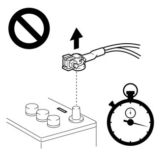 NOTICE: When disconnecting the cable, some systems need to be initialized after the cable is reconnected. Click here 4. REMOVE FRONT DOOR SCUFF PLATE RH HINT: Use the same procedure as for the LH side. Click here
5. REMOVE COWL SIDE TRIM SUB-ASSEMBLY RH HINT: Use the same procedure as for the LH side. Click here
6. DISCONNECT FRONT DOOR OPENING TRIM WEATHERSTRIP RH HINT: Disconnect the front door opening trim weatherstrip RH to the extent that allows the removal of the instrument side panel RH. 7. REMOVE GLOVE COMPARTMENT PLATE Click here
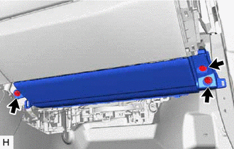
8. REMOVE INSTRUMENT SIDE PANEL RH Click here 9. REMOVE NO. 2 INSTRUMENT PANEL UNDER COVER SUB-ASSEMBLY Click here 10. REMOVE INSTRUMENT PANEL FINISH PANEL END LH Click here 11. REMOVE LOWER NO. 2 INSTRUMENT PANEL AIRBAG ASSEMBLY CAUTION: When storing the lower No. 2 instrument panel airbag assembly, keep the airbag deployment side facing upward. 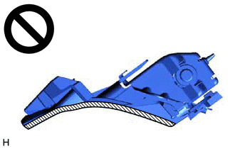
(a) Check that the engine switch (for Gasoline Model) or power switch (for HV Model) is off. (b) Check that the cable is disconnected from the negative (-) auxiliary battery terminal. CAUTION: Wait at least 90 seconds after disconnecting the cable from the negative (-) auxiliary battery terminal to disable the SRS system.
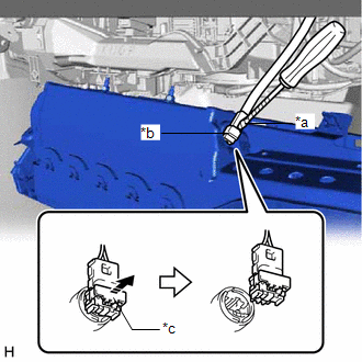
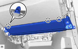
(e) Using a screwdriver with its tip wrapped with protective tape, release the airbag connector locking button. (f) Disconnect the airbag connector to remove the lower No. 2 instrument panel airbag assembly. NOTICE: When disconnecting any airbag connector, take care not to damage the airbag wire harness. | ||||||||||||||||||||||||||||||||||||||||||||||||||||||||
Toyota Avalon (XX50) 2019-2022 Service & Repair Manual > Intelligent Clearance Sonar System(for Gasoline Model): Stop Light Relay Circuit (C1A4B)
DESCRIPTION When a stop light relay circuit malfunction signal sent from the electronically controlled brake system is detected by the clearance warning ECU assembly, DTC C1A4B is stored. DTC No. Detection Item DTC Detection Condition Trouble Area C1A4B Stop Light Relay Circuit Stop light relay circ ...