REMOVAL CAUTION / NOTICE / HINT
The
necessary procedures (adjustment, calibration, initialization or
registration) that must be performed after parts are removed and
installed, or replaced during spiral cable sub-assembly
removal/installation are shown below. Necessary Procedures After Parts Removed/Installed/Replaced (for Gasoline Model) |
Replaced Part or Performed Procedure |
Necessary Procedure | Effect/Inoperative Function when Necessary Procedure not Performed |
Link | |
*: When performing learning using the Techstream.
Click here  | |
Removal/installation of the spiral cable with sensor sub-assembly |
Steering angle zero point learning (Initialize intelligent clearance sonar system) |
- Intelligent Clearance Sonar System
- Intuitive Parking Assist System
|
|
- Steering angle zero point learning (Initialize parking assist monitor system)
- Steering angle setting
| Parking Assist Monitor System |
for Initialization
for Calibration | |
Steering angle zero point learning (Initialize panoramic view monitor system) |
Panoramic View Monitor System |
for Initialization
for Calibration | |
Disconnect cable from negative auxiliary battery terminal |
Perform steering sensor zero point calibration |
Lane Departure Alert System (w/ Steering Control) |
| |
Pre-collision System | |
Intelligent Clearance Sonar System* | |
Lighting System (for Gasoline Model with Cornering Light) | |
Memorize steering angle neutral point |
Parking Assist Monitor System |
| |
Panoramic View Monitor System |
| Necessary Procedures After Parts Removed/Installed/Replaced (for HV Model) |
Replaced Part or Performed Procedure |
Necessary Procedure | Effect/Inoperative Function when Necessary Procedure not Performed |
Link | |
*: When performing learning using the Techstream.
Click here | |
Removal/installation of the spiral cable with sensor sub-assembly |
Steering angle zero point learning (Initialize intelligent clearance sonar system) |
- Intelligent Clearance Sonar System
- Intuitive Parking Assist System
|
|
- Steering angle zero point learning (Initialize parking assist monitor system)
- Steering angle setting
| Parking Assist Monitor System |
for Initialization
for Calibration | |
Steering angle zero point learning (Initialize panoramic view monitor system) |
Panoramic View Monitor System |
for Initialization
for Calibration | |
Disconnect cable from negative auxiliary battery terminal |
Perform steering sensor zero point calibration |
Lane Departure Alert System (w/ Steering Control) |
| |
Pre-collision System | |
Intelligent Clearance Sonar System* | |
Lighting System (for HV Model with Cornering Light) | |
Memorize steering angle neutral point |
Parking Assist Monitor System |
| |
Panoramic View Monitor System |
| PROCEDURE
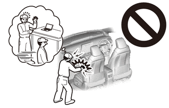
1. PRECAUTION CAUTION: Be sure to read Precaution thoroughly before servicing.
for Gasoline Model: Click here for HV Model: Click here
 NOTICE: After
turning the engine switch (for Gasoline Model) or power switch (for HV
Model) off, waiting time may be required before disconnecting the cable
from the negative (-) auxiliary battery terminal. Therefore, make sure
to read the disconnecting the cable from the negative (-) auxiliary
battery terminal notices before proceeding with work. Click here
2. CHANGE POWER TILT AND POWER TELESCOPIC STEERING COLUMN SYSTEM SETTINGS (for Power Tilt and Power Telescopic Steering Column)
Click here 3. ALIGN FRONT WHEELS FACING STRAIGHT AHEAD
4. REMOVE LUGGAGE TRIM SERVICE HOLE COVER (for HV Model) Click here
5. DISCONNECT CABLE FROM NEGATIVE AUXILIARY BATTERY TERMINAL
for Gasoline Model: Click here for HV Model: Click here
CAUTION: Wait
at least 90 seconds after disconnecting the cable from the negative (-)
auxiliary battery terminal to disable the SRS system.
 NOTICE: When disconnecting the cable, some systems need to be initialized after the cable is reconnected.
Click here 6. REMOVE LOWER NO. 2 STEERING WHEEL COVER
Click here 7. REMOVE HORN BUTTON ASSEMBLY
Click here 8. REMOVE STEERING WHEEL ASSEMBLY
Click here 9. REMOVE LOWER STEERING COLUMN COVER (for Manual Tilt and Manual Telescopic Steering Column)
Click here 10. REMOVE LOWER STEERING COLUMN COVER (for Power Tilt and Power Telescopic Steering Column)
Click here 11. REMOVE UPPER STEERING COLUMN COVER (for Manual Tilt and Manual Telescopic Steering Column)
Click here 12. REMOVE UPPER STEERING COLUMN COVER (for Power Tilt and Power Telescopic Steering Column)
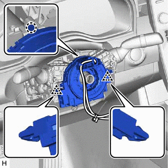
Click here 13. REMOVE SPIRAL CABLE WITH SENSOR SUB-ASSEMBLY
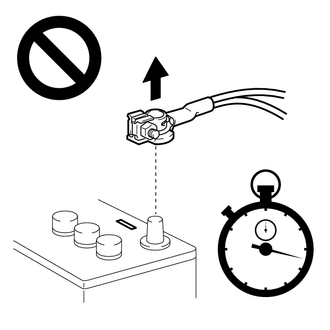
NOTICE:
- Do not remove/install the spiral cable with sensor sub-assembly with the
auxiliary battery connected and the engine switch (for Gasoline Model)
or power switch (for HV Model) on (IG).
- Do not rotate the spiral cable with sensor sub-assembly without the
steering wheel assembly installed, with the auxiliary battery connected
and the engine switch (for Gasoline Model) or power switch (for HV
Model) on (IG).
- Ensure that the steering wheel assembly is installed and aligned straight when inspecting the steering sensor.
(a) Check that the engine switch (for Gasoline Model) or power switch (for HV Model) is off.
(b) Check that the cable is disconnected from the negative (-) auxiliary battery terminal.
CAUTION: Wait
at least 90 seconds after disconnecting the cable from the negative (-)
auxiliary battery terminal to disable the SRS system.
(c) Check that the front wheels are aligned facing straight ahead.
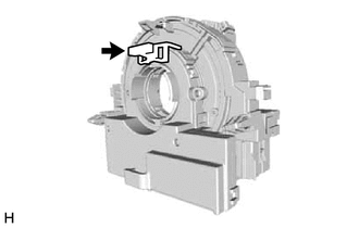
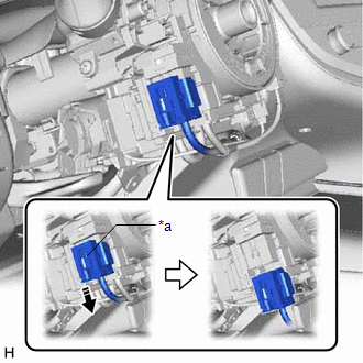
(d)
Slide the slider to release the lock, and then disconnect the yellow
airbag connector from the spiral cable with sensor sub-assembly.
|
*a | Slider |
 |
Release in this Direction | NOTICE:
When disconnecting any airbag connector, take care not to damage the airbag wire harness.
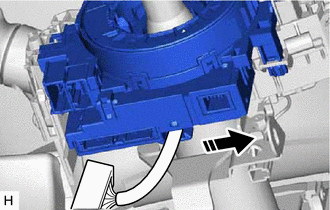
(e) Disconnect the other connectors from the spiral cable with sensor sub-assembly.
(f) Separate the wire harness from the spiral cable with sensor sub-assembly as shown in the illustration.
|
|
Separate in this Direction |
| (g) Disengage the claw and 2 clips to remove the spiral cable with sensor sub-assembly. |
|
14. REMOVE SPIRAL CABLE SUB-ASSEMBLY
NOTICE:
- Remove the steering sensor from the spiral cable sub-assembly only when
replacing the spiral cable sub-assembly or the steering sensor.
- Removing the steering sensor from the spiral cable sub-assembly without
using a lock pin may result in the center position of the steering
sensor becoming misaligned. Therefore, make sure to use the lock pin
provided with a new spiral cable sub-assembly when removing the steering
sensor from the spiral cable sub-assembly.
- When replacing the steering sensor:
Click here
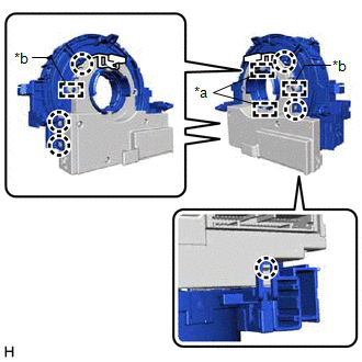
| (a) Install the lock pin to the steering sensor.
NOTICE:
- Use the lock pin provided with a new spiral cable sub-assembly.
- Do not remove the lock pin before installing the steering sensor to the spiral cable sub-assembly.
| |
| (b) Disengage the 6 claws and 2 pins to remove the spiral cable sub-assembly from the steering sensor.
NOTICE: Do not damage the pins of the spiral cable sub-assembly or guides of the steering sensor. |
| |