Toyota Avalon (XX50) 2019-2022 Service & Repair Manual: AVC-LAN Circuit

DESCRIPTION

Each unit of the navigation system connected to the AVC-LAN (communication bus) transmits signals via AVC-LAN communication.

If a short to +B or short to ground occurs in an AVC-LAN communication line, the navigation system will not function normally because communication is not possible.

WIRING DIAGRAM

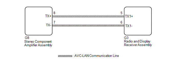
CAUTION / NOTICE / HINT

NOTICE:

  • Depending on the parts that are replaced during vehicle inspection or maintenance, performing initialization, registration or calibration may be needed. Refer to Precaution for Navigation System.

    Click here

  • When replacing the radio and display receiver assembly, always replace it with a new one. If a radio and display receiver assembly which was installed to another vehicle is used, the following may occur:
    • A communication malfunction DTC may be stored.
    • The radio and display receiver assembly may not operate normally.

HINT:

The radio and display receiver assembly is the master unit.

PROCEDURE

1.

INSPECT RADIO AND DISPLAY RECEIVER ASSEMBLY

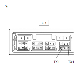
(a) Remove the radio and display receiver assembly.

(b) Measure the resistance according to the value(s) in the table below.

Standard Resistance:

Tester Connection

Condition

Specified Condition

G3-5 (TX1+) - G3-6 (TX1-)

Always

60 to 80 Ω

*a

Component without harness connected

(Radio and Display Receiver Assembly)

NG

REPLACE RADIO AND DISPLAY RECEIVER ASSEMBLY

OK

2.

CHECK HARNESS AND CONNECTOR (AVC-LAN CIRCUIT)

(a) Disconnect the G3 radio and display receiver assembly connector.

(b) Disconnect the G8 stereo component amplifier assembly connector.

(c) Measure the resistance according to the value(s) in the table below.

Standard Resistance:

Tester Connection

Condition

Specified Condition

G8-8 (TX+) - G3-5 (TX1+)

Always

Below 1 Ω

G8-7 (TX-) - G3-6 (TX1-)

Always

Below 1 Ω

G8-8 (TX+) or G3-5 (TX1+) - Body ground

Always

10 kΩ or higher

G8-7 (TX-) or G3-6 (TX1-) - Body ground

Always

10 kΩ or higher

NG

REPAIR OR REPLACE HARNESS OR CONNECTOR

OK

3.

INSPECT MALFUNCTIONING PARTS

(a) Disconnect and reconnect each slave unit one by one until the master unit returns to normal.

HINT:

  • Check all slave units.
  • If disconnecting a slave unit causes the master unit to return to normal, the slave unit is defective and should be replaced.

OK:

Master unit returns to normal.

OK

REPLACE MALFUNCTIONING PARTS

NG

REPLACE RADIO AND DISPLAY RECEIVER ASSEMBLY

    "No GPS signal" mark is displayed

    Stereo Component Amplifier Malfunction (B15A3)

    See More:

    Toyota Avalon (XX50) 2019-2022 Service & Repair Manual > Sfi System: Camshaft Position Sensor "B" Bank 1 Circuit Short to Ground (P036511,P036515,P039011,P039015)
    DESCRIPTION The VVT sensor (for exhaust camshaft) (EV1, EV2 signal) consists of a magnet and MRE (Magneto Resistance Element). The exhaust camshaft has a timing rotor for the VVT sensor. When the exhaust camshaft rotates, changes occur in the air gaps between the timing rotor and MRE, which affects ...

    Toyota Avalon (XX50) 2019-2022 Owners Manual

    Toyota Avalon (XX50) 2019-2022 Service & Repair Manual

    © 2024 Copyright www.tavalon.net
    0.0137