DESCRIPTION This DTC is stored when a malfunction occurs in the speakers. |
DTC No. | Detection Item |
DTC Detection Condition | Trouble Area | |
B15C3 | Speaker Output Short |
A short is detected in the speaker output circuit |
- Harness or connector
- Speaker
- DCM (telematics transceiver)*
- Stereo Component Amplifier
|
- *: w/ Manual (SOS) Switch
WIRING DIAGRAM

 CAUTION / NOTICE / HINT
NOTICE:
- Depending on the parts that are replaced during vehicle inspection or
maintenance, performing initialization, registration or calibration may
be needed. Refer to Precaution for Navigation System.
Click here 
- When replacing the radio and display receiver assembly, always replace
it with a new one. If a radio and display receiver assembly which was
installed to another vehicle is used, the following may occur:
- A communication malfunction DTC may be stored.
- The radio and display receiver assembly may not operate normally.
- Before replacing the DCM (telematics transceiver), refer to Registration.
Click here
PROCEDURE (a) Choose the model to be inspected.
|
Result | Proceed to | |
w/ Manual (SOS) Switch |
A | | w/o Manual (SOS) Switch |
B |
| B |
 | GO TO STEP 5 |
|
A |
 | |
| 2. |
CHECK HARNESS AND CONNECTOR (STEREO COMPONENT AMPLIFIER ASSEMBLY, DCM (TELEMATICS TRANSCEIVER) OR SPEAKERS - BODY GROUND) |
(a) Disconnect the G10 stereo component amplifier assembly connector. (b) Disconnect the G9 DCM (telematics transceiver) connector.
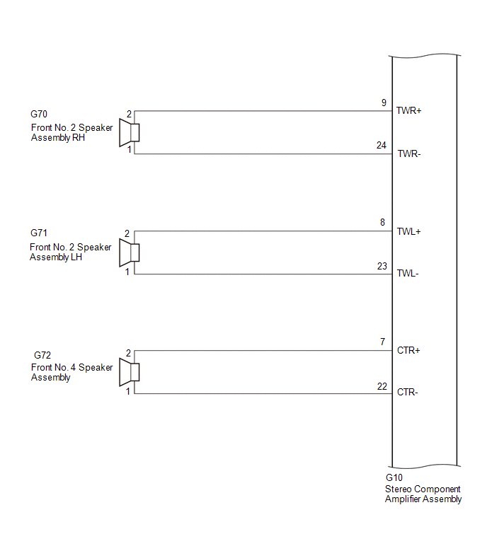
(c) Disconnect the G70 and G71 front No. 2 speaker assembly connectors.
(d) Disconnect the G72 front No. 4 speaker assembly connector. (e) Disconnect the G79 front No. 3 speaker assembly LH connector.
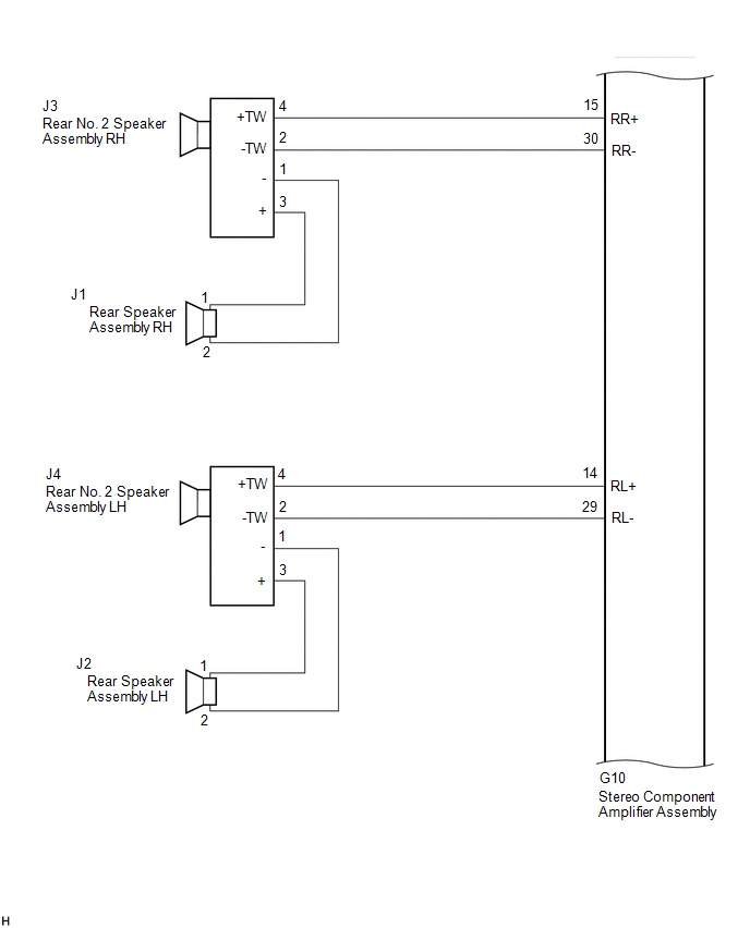
(f) Disconnect the J3 and J4 rear No. 2 speaker assembly connectors. (g) Disconnect the K2 and K3 speaker assembly with bracket connectors.
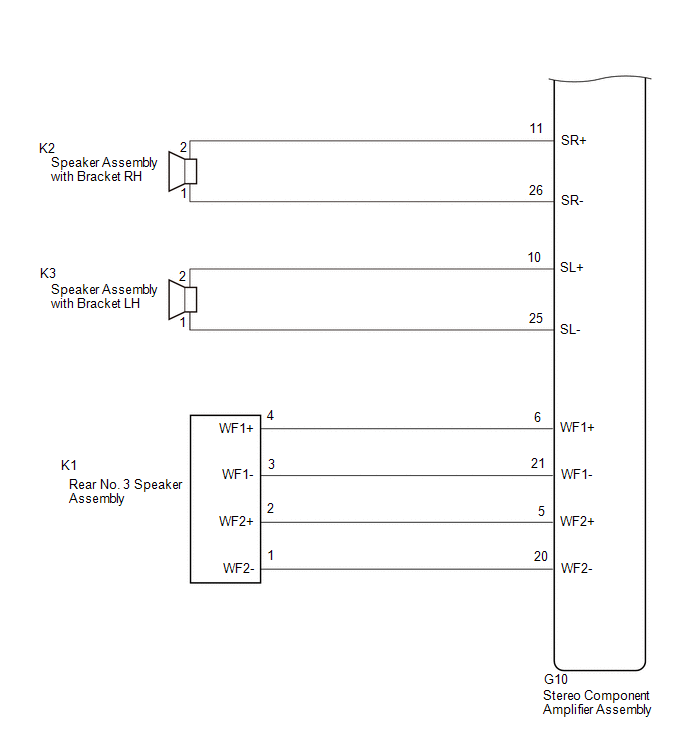
(h) Disconnect the K1 rear No. 3 speaker assembly connector. (i) Measure the resistance according to the value(s) in the table below.
Standard Resistance: |
Tester Connection | Condition |
Specified Condition | |
G10-9 (TWR+) or G70-2 - Body ground |
Always | 10 kΩ or higher | |
G10-24 (TWR-) or G70-1 - Body ground |
Always | 10 kΩ or higher | |
G10-8 (TWL+) or G71-2 - Body ground |
Always | 10 kΩ or higher | |
G10-23 (TWL-) or G71-1 - Body ground |
Always | 10 kΩ or higher | |
G10-13 (FR+) or G9-2 (SPI+) - Body ground |
Always | 10 kΩ or higher | |
G10-28 (FR-) or G9-3 (SPI-) - Body ground |
Always | 10 kΩ or higher | |
G10-12 (FL+) or G79-4 (+TW) - Body ground |
Always | 10 kΩ or higher | |
G10-27 (FL-) or G79-2 (-TW) - Body ground |
Always | 10 kΩ or higher | |
G10-15 (RR+) or J3-4 (+TW) - Body ground |
Always | 10 kΩ or higher | |
G10-30 (RR-) or J3-2 (-TW) - Body ground |
Always | 10 kΩ or higher | |
G10-14 (RL+) or J4-4 (+TW) - Body ground |
Always | 10 kΩ or higher | |
G10-29 (RL-) or J4-2 (-TW) - Body ground |
Always | 10 kΩ or higher | |
G10-6 (WF1+) or K1-4 (WF1+) - Body ground |
Always | 10 kΩ or higher | |
G10-21 (WF1-) or K1-3 (WF1-) - Body ground |
Always | 10 kΩ or higher | |
G10-5 (WF2+) or K1-2 (WF2+) - Body ground |
Always | 10 kΩ or higher | |
G10-20 (WF2-) or K1-1 (WF2-) - Body ground |
Always | 10 kΩ or higher | |
G10-7 (CTR+) or G72-2 - Body ground |
Always | 10 kΩ or higher | |
G10-22 (CTR-) or G72-1 - Body ground |
Always | 10 kΩ or higher | |
G10-11 (SR+) or K2-2 - Body ground |
Always | 10 kΩ or higher | |
G10-26 (SR-) or K2-1 - Body ground |
Always | 10 kΩ or higher | |
G10-10 (SL+) or K3-2 - Body ground |
Always | 10 kΩ or higher | |
G10-25 (SL-) or K3-1 - Body ground |
Always | 10 kΩ or higher |
| NG |
| REPAIR OR REPLACE HARNESS OR CONNECTOR |
|
OK | |
| |
| 3. |
CHECK HARNESS AND CONNECTOR (DCM (TELEMATICS TRANSCEIVER) OR SPEAKER - BODY GROUND) |
(a) Disconnect the G9 DCM (telematics transceiver) connector. (b) Disconnect the G78 front No. 3 speaker assembly RH connector.
(c) Measure the resistance according to the value(s) in the table below.
Standard Resistance: |
Tester Connection | Condition |
Specified Condition | |
G9-5 (SPO+) or G78-4 (+TW) - Body ground |
Always | 10 kΩ or higher | |
G9-6 (SPO-) or G78-2 (-TW) - Body ground |
Always | 10 kΩ or higher |
| NG |
| REPAIR OR REPLACE HARNESS OR CONNECTOR |
|
OK | |
| |
| 4. |
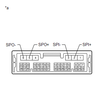
INSPECT DCM (TELEMATICS TRANSCEIVER) | (a) Remove the DCM (telematics transceiver).
Click here
| (b) Measure the resistance according to the value(s) in the table below.
Standard Resistance: |
Tester Connection | Condition |
Specified Condition | |
2 (SPI+) - 5 (SPO+) |
Always | Below 1 Ω | |
3 (SPI-) - 6 (SPO-) |
Always | Below 1 Ω | |
2 (SPI+) - 3 (SPI-) |
Always | 10 kΩ or higher | |
5 (SPO+) - 6 (SPO-) |
Always | 10 kΩ or higher | |
2 (SPI+) or 5 (SPO+) - Body ground |
Always | 10 kΩ or higher | |
3 (SPI-) or 6 (SPO-) - Body ground |
Always | 10 kΩ or higher | |
 |
|
*a | Component without harness connected
(DCM (Telematics Transceiver)) | | |
| OK |
| GO TO STEP 6 |
| NG |
| REPLACE DCM (TELEMATICS TRANSCEIVER) |
| 5. |
CHECK HARNESS AND CONNECTOR (STEREO COMPONENT AMPLIFIER ASSEMBLY OR SPEAKERS - BODY GROUND) |
(a) Disconnect the G10 stereo component amplifier assembly connector. (b) Disconnect the G78 and G79 front No. 3 speaker assembly connectors.
(c) Disconnect the G70 and G71 front No. 2 speaker assembly connectors.
(d) Disconnect the J3 and J4 rear No. 2 speaker assembly connectors. (e) Disconnect the K2 and K3 speaker assembly with bracket connectors.
(f) Disconnect the K1 rear No. 3 speaker assembly connector. (g) Disconnect the G72 front No. 4 speaker assembly connector.
(h) Measure the resistance according to the value(s) in the table below.
Standard Resistance: |
Tester Connection | Condition |
Specified Condition | |
G10-13 (FR+) or G78-4 (+TW) - Body ground |
Always | 10 kΩ or higher | |
G10-28 (FR-) or G78-2 (-TW) - Body ground |
Always | 10 kΩ or higher | |
G10-12 (FL+) or G79-4 (+TW) - Body ground |
Always | 10 kΩ or higher | |
G10-27 (FL-) or G79-2 (-TW) - Body ground |
Always | 10 kΩ or higher | |
G10-9 (TWR+) or G70-2 - Body ground |
Always | 10 kΩ or higher | |
G10-24 (TWR-) or G70-1 - Body ground |
Always | 10 kΩ or higher | |
G10-8 (TWL+) or G71-2 - Body ground |
Always | 10 kΩ or higher | |
G10-23 (TWL-) or G71-1 - Body ground |
Always | 10 kΩ or higher | |
G10-15 (RR+) or J3-4 (+TW) - Body ground |
Always | 10 kΩ or higher | |
G10-30 (RR-) or J3-2 (-TW) - Body ground |
Always | 10 kΩ or higher | |
G10-14 (RL+) or J4-4 (+TW) - Body ground |
Always | 10 kΩ or higher | |
G10-29 (RL-) or J4-2 (-TW) - Body ground |
Always | 10 kΩ or higher | |
G10-6 (WF1+) or K1-4 (WF1+) - Body ground |
Always | 10 kΩ or higher | |
G10-21 (WF1-) or K1-3 (WF1-) - Body ground |
Always | 10 kΩ or higher | |
G10-5 (WF2+) or K1-2 (WF2+) - Body ground |
Always | 10 kΩ or higher | |
G10-20 (WF2-) or K1-1 (WF2-) - Body ground |
Always | 10 kΩ or higher |
| NG |
| REPAIR OR REPLACE HARNESS OR CONNECTOR |
|
OK | |
| |
| 6. |
CHECK HARNESS AND CONNECTOR (FRONT NO. 1 SPEAKER ASSEMBLY OR FRONT NO. 3 SPEAKER ASSEMBLY - BODY GROUND) |
(a) Disconnect the I1 and I15 front No. 1 speaker assembly connectors.
(b) Disconnect the G78 and G79 front No. 3 speaker assembly connectors.
(c) Measure the resistance according to the value(s) in the table below.
Standard Resistance: |
Tester Connection | Condition |
Specified Condition | |
I1-2 or G78-3 (+) - Body ground |
Always | 10 kΩ or higher | |
I1-1 or G78-1 (-) - Body ground |
Always | 10 kΩ or higher | |
I15-2 or G79-3 (+) - Body ground |
Always | 10 kΩ or higher | |
I15-1 or G79-1 (-) - Body ground |
Always | 10 kΩ or higher |
| NG |
| REPAIR OR REPLACE HARNESS OR CONNECTOR |
|
OK | |
| |
| 7. |
CHECK HARNESS AND CONNECTOR (REAR SPEAKER ASSEMBLY OR REAR NO. 2 SPEAKER ASSEMBLY - BODY GROUND) |
(a) Disconnect the J3 and J4 rear No. 2 speaker assembly connectors. (b) Disconnect the J1 and J2 rear speaker assembly connectors.
(c) Measure the resistance according to the value(s) in the table below.
Standard Resistance: |
Tester Connection | Condition |
Specified Condition | |
J1-1 or J3-3 (+) - Body ground |
Always | 10 kΩ or higher | |
J1-2 or J3-1 (-) - Body ground |
Always | 10 kΩ or higher | |
J2-1 or J4-3 (+) - Body ground |
Always | 10 kΩ or higher | |
J2-2 or J4-1 (-) - Body ground |
Always | 10 kΩ or higher |
| NG |
| REPAIR OR REPLACE HARNESS OR CONNECTOR |
|
OK | |
| |
| 8. |
INSPECT FRONT NO. 1 SPEAKER ASSEMBLY | (a) Remove the front No. 1 speaker assembly.
Click here (b) Inspect the front No. 1 speaker assembly.
Click here
| NG |
| REPLACE FRONT NO. 1 SPEAKER ASSEMBLY |
|
OK | |
| |
| 9. |
INSPECT FRONT NO. 2 SPEAKER ASSEMBLY | (a) Remove the front No. 2 speaker assembly.
Click here (b) Inspect the front No. 2 speaker assembly.
Click here
| NG |
| REPLACE FRONT NO. 2 SPEAKER ASSEMBLY |
|
OK | |
| |
| 10. |
INSPECT FRONT NO. 4 SPEAKER ASSEMBLY | (a) Remove the front No. 4 speaker assembly.
Click here (b) Inspect the front No. 4 speaker assembly.
Click here
| NG |
| REPLACE FRONT NO. 4 SPEAKER ASSEMBLY |
|
OK | |
| |
| 11. |
INSPECT REAR SPEAKER ASSEMBLY | (a) Remove the rear speaker assembly.
Click here (b) Inspect the rear speaker assembly.
Click here
| NG |
| REPLACE REAR SPEAKER ASSEMBLY |
|
OK | |
| |
| 12. |
INSPECT REAR NO. 3 SPEAKER ASSEMBLY | (a) Remove the rear No. 3 speaker assembly.
Click here (b) Inspect the rear No. 3 speaker assembly.
Click here
| NG |
| REPLACE REAR NO. 3 SPEAKER ASSEMBLY |
|
OK | |
| |
| 13. |
INSPECT SPEAKER ASSEMBLY WITH BRACKET |
(a) Remove the speaker assembly with bracket. Click here
(b) Inspect the speaker assembly with bracket.
Click here
| NG |
| REPLACE SPEAKER ASSEMBLY WITH BRACKET |
|
OK | |
| |
| 14. |
REPLACE FRONT NO. 3 SPEAKER ASSEMBLY | (a) Remove the front No. 3 speaker assembly.
Click here (b) Inspect the front No. 3 speaker assembly.
Click here (c) Clear the DTCs. Body Electrical > Navigation System > Clear DTCs
(d) Recheck for DTCs and check that no DTCs are output. Body Electrical > Navigation System > Trouble Codes
OK: No DTCs are output.
| OK | |
END |
|
NG | |
| |
| 15. |
REPLACE REAR NO. 2 SPEAKER ASSEMBLY | (a) Remove the rear No. 2 speaker assembly.
Click here (b) Inspect the rear No. 2 speaker assembly.
Click here (c) Clear the DTCs. Body Electrical > Navigation System > Clear DTCs
(d) Recheck for DTCs and check that no DTCs are output. Body Electrical > Navigation System > Trouble Codes
OK: No DTCs are output.
| OK | |
END |
| NG |
| REPLACE STEREO COMPONENT AMPLIFIER ASSEMBLY | | 

