DESCRIPTION This circuit includes the navigation ECU and radio and display receiver assembly. WIRING DIAGRAM 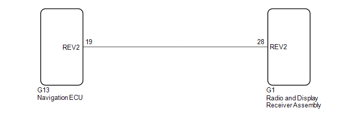 PROCEDURE
(a) Disconnect the G1 radio and display receiver assembly connector. (b) Disconnect the G13 navigation ECU connector. (c) Measure the resistance according to the value(s) in the table below. Standard Resistance:
|
Toyota Avalon (XX50) 2019-2022 Service & Repair Manual > Hybrid Control System: Lost Communication with Hybrid/EV Battery Sensor Module Missing Message (U029A87)
DESCRIPTION The battery voltage sensor detects the HV battery conditions (voltage, current and temperature) and the battery cooling fan frequency, and sends the detected signals to the hybrid vehicle control ECU via serial communication. (The hybrid vehicle control ECU does not send signals to the b ...


