DESCRIPTION If there is a short in a speaker circuit, the stereo component amplifier assembly detects it and stops output to the speakers.
Thus
sound cannot be heard from the speakers even if there is no malfunction
in the stereo component amplifier assembly, DCM (telematics
transceiver)* or speakers.
- *: w/ Manual (SOS) Switch
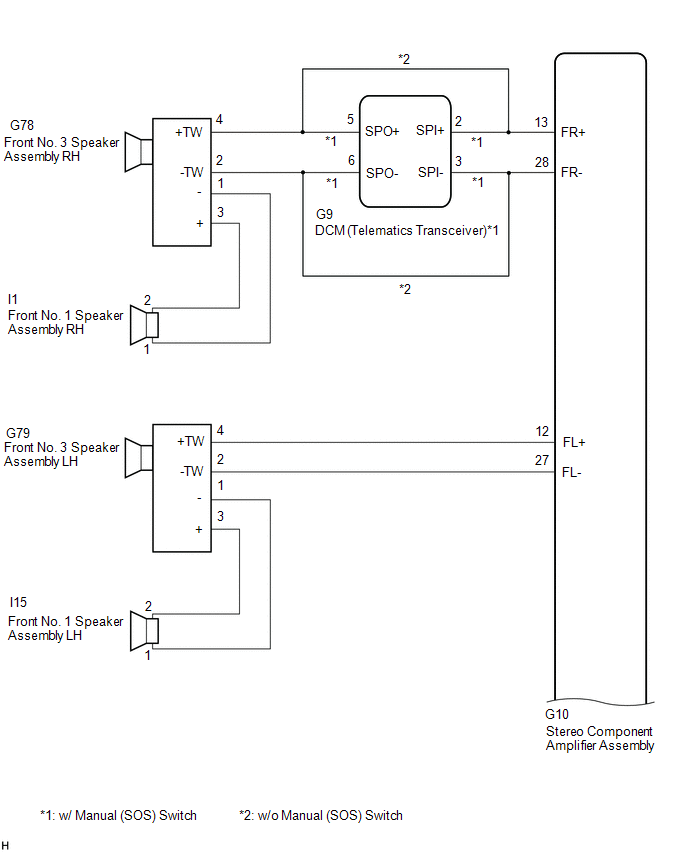
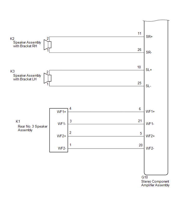
WIRING DIAGRAM
 CAUTION / NOTICE / HINT
NOTICE:
- Depending on the parts that are replaced during vehicle inspection or
maintenance, performing initialization, registration or calibration may
be needed. Refer to Precaution for Navigation System.
Click here 
- Before replacing the DCM (telematics transceiver), refer to Registration.
Click here
PROCEDURE |
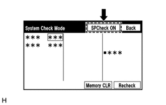
1. | CHECK SPEAKER (OPERATION CHECK) |
| (a) Enter the "System Check Mode" screen. Refer to Check Speaker in Operation Check.
Click here | |
(b) Perform the operation check above and determine the speaker that is not operating.
|
Not Operating Speaker | Proceed to | |
Front No. 1 speaker assembly or front No. 3 speaker assembly (w/ Manual (SOS) Switch) |
A | | Front No. 1 speaker assembly or front No. 3 speaker assembly
(w/o Manual (SOS) Switch) |
B | | Front No. 2 speaker assembly |
C | | Front No. 4 speaker assembly |
D | | Rear speaker assembly or rear No. 2 speaker assembly |
E | | Speaker assembly with bracket |
F | | Rear No. 3 speaker assembly |
G | HINT: If sound cannot be heard from any speaker, inspect all of them.
| B |
 | GO TO STEP 6 |
| C |
| GO TO STEP 9 |
| D |
| GO TO STEP 11 |
| E |
| GO TO STEP 13 |
| F |
| GO TO STEP 16 |
| G |
| GO TO STEP 18 |
|
A |
 | |
| 2. |
CHECK
HARNESS AND CONNECTOR (STEREO COMPONENT AMPLIFIER ASSEMBLY - FRONT NO. 1
SPEAKER ASSEMBLY - FRONT NO. 3 SPEAKER ASSEMBLY - DCM (TELEMATICS
TRANSCEIVER)) | (a) Disconnect the G10 stereo component amplifier assembly connector.
(b) Disconnect the I1 and I15 front No. 1 speaker assembly connectors.
(c) Disconnect the G78 and G79 front No. 3 speaker assembly connectors.
(d) Disconnect the G9 DCM (telematics transceiver) connector. (e) Measure the resistance according to the value (s) in the table below.
Standard Resistance: |
Tester Connection | Condition |
Specified Condition | |
G10-13 (FR+) - G9-2 (SPI+) |
Always | Below 1 Ω | |
G10-28 (FR-) - G9-3 (SPI-) |
Always | Below 1 Ω | |
G9-5 (SPO+) - G78-4 (+TW) |
Always | Below 1 Ω | |
G9-6 (SPO-) - G78-2 (-TW) |
Always | Below 1 Ω | |
G10-12 (FL+) - G79-4 (+TW) |
Always | Below 1 Ω | |
G10-27 (FL-) - G79-2 (-TW) |
Always | Below 1 Ω | |
I1-2 - G78-3 (+) | Always |
Below 1 Ω | |
I1-1 - G78-1 (-) | Always |
Below 1 Ω | |
I15-2 - G79-3 (+) | Always |
Below 1 Ω | |
I15-1 - G79-1 (-) | Always |
Below 1 Ω | |
G10-13 (FR+) or G9-2 (SPI+) - Body ground |
Always | 10 kΩ or higher | |
G10-28 (FR-) or G9-3 (SPI-) - Body ground |
Always | 10 kΩ or higher | |
G9-5 (SPO+) or G78-4 (+TW) - Body ground |
Always | 10 kΩ or higher | |
G9-6 (SPO-) or G78-2 (-TW) - Body ground |
Always | 10 kΩ or higher | |
G10-12 (FL+) or G79-4 (+TW) - Body ground |
Always | 10 kΩ or higher | |
G10-27 (FL-) or G79-2 (-TW) - Body ground |
Always | 10 kΩ or higher | |
I1-2 or G78-3 (+) - Body ground |
Always | 10 kΩ or higher | |
I1-1 or G78-1 (-) - Body ground |
Always | 10 kΩ or higher | |
I15-2 or G79-3 (+) - Body ground |
Always | 10 kΩ or higher | |
I15-1 or G79-1 (-) - Body ground |
Always | 10 kΩ or higher |
| NG |
| REPAIR OR REPLACE HARNESS OR CONNECTOR |
|
OK | |
| |
| 3. |
INSPECT FRONT NO. 1 SPEAKER ASSEMBLY | (a) Remove the front No. 1 speaker assembly.
Click here (b) Inspect the front No. 1 speaker assembly.
Click here
| NG |
| REPLACE FRONT NO. 1 SPEAKER ASSEMBLY |
|
OK | |
| |
| 4. |
INSPECT DCM (TELEMATICS TRANSCEIVER) | (a) Remove the DCM (telematics transceiver).
Click here
| (b) Measure the resistance according to the value(s) in the table below.
Standard Resistance: |
Tester Connection | Condition |
Specified Condition | |
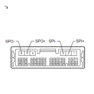
2 (SPI+) - 5 (SPO+) |
Always | Below 1 Ω | |
3 (SPI-) - 6 (SPO-) |
Always | Below 1 Ω | |
2 (SPI+) - 3 (SPI-) |
Always | 10 kΩ or higher | |
5 (SPO+) - 6 (SPO-) |
Always | 10 kΩ or higher | |
2 (SPI+) or 5 (SPO+) - Body ground |
Always | 10 kΩ or higher | |
3 (SPI-) or 6 (SPO-) - Body ground |
Always | 10 kΩ or higher | |
 |
|
*a | Component without harness connected
(DCM (Telematics Transceiver)) | | |
| NG |
| REPLACE DCM (TELEMATICS TRANSCEIVER) |
|
OK | |
| |
| 5. |
REPLACE FRONT NO. 3 SPEAKER ASSEMBLY | (a) Remove the front No. 3 speaker assembly.
Click here (b) Inspect the front No. 3 speaker assembly.
Click here OK: Malfunction disappears.
| OK |
| END |
| NG |
| PROCEED TO NEXT SUSPECTED AREA SHOWN IN PROBLEM SYMPTOMS TABLE |
| 6. |
CHECK HARNESS AND CONNECTOR (STEREO COMPONENT AMPLIFIER ASSEMBLY - FRONT NO. 1 SPEAKER ASSEMBLY - FRONT NO. 3 SPEAKER ASSEMBLY) |
(a) Disconnect the G10 stereo component amplifier assembly connector. (b) Disconnect the I1 and I15 front No. 1 speaker assembly connectors.
(c) Disconnect the G78 and G79 front No. 3 speaker assembly connectors.
(d) Measure the resistance according to the value (s) in the table below.
Standard Resistance: |
Tester Connection | Condition |
Specified Condition | |
G10-13 (FR+) - G78-4 (+TW) |
Always | Below 1 Ω | |
G10-28 (FR-) - G78-2 (-TW) |
Always | Below 1 Ω | |
G10-12 (FL+) - G79-4 (+TW) |
Always | Below 1 Ω | |
G10-27 (FL-) - G79-2 (-TW) |
Always | Below 1 Ω | |
I1-2 - G78-3 (+) | Always |
Below 1 Ω | |
I1-1 - G78-1 (-) | Always |
Below 1 Ω | |
I15-2 - G79-3 (+) | Always |
Below 1 Ω | |
I15-1 - G79-1 (-) | Always |
Below 1 Ω | |
G10-13 (FR+) or G78-4 (+TW) - Body ground |
Always | 10 kΩ or higher | |
G10-28 (FR-) or G78-2 (-TW) - Body ground |
Always | 10 kΩ or higher | |
G10-12 (FL+) or G79-4 (+TW) - Body ground |
Always | 10 kΩ or higher | |
G10-27 (FL-) or G79-2 (-TW) - Body ground |
Always | 10 kΩ or higher | |
I1-2 or G78-3 (+) - Body ground |
Always | 10 kΩ or higher | |
I1-1 or G78-1 (-) - Body ground |
Always | 10 kΩ or higher | |
I15-2 or G79-3 (+) - Body ground |
Always | 10 kΩ or higher | |
I15-1 or G79-1 (-) - Body ground |
Always | 10 kΩ or higher |
| NG |
| REPAIR OR REPLACE HARNESS OR CONNECTOR |
|
OK | |
| |
| 7. |
INSPECT FRONT NO. 1 SPEAKER ASSEMBLY | (a) Remove the front No. 1 speaker assembly.
Click here (b) Inspect the front No. 1 speaker assembly.
Click here
| NG |
| REPLACE FRONT NO. 1 SPEAKER ASSEMBLY |
|
OK | |
| |
| 8. |
REPLACE FRONT NO. 3 SPEAKER ASSEMBLY | (a) Remove the front No. 3 speaker assembly.
Click here (b) Inspect the front No. 3 speaker assembly.
Click here OK: Malfunction disappears.
| OK |
| END |
| NG |
| PROCEED TO NEXT SUSPECTED AREA SHOWN IN PROBLEM SYMPTOMS TABLE |
| 9. |
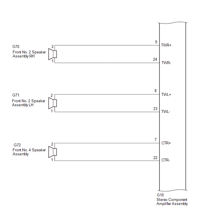
CHECK HARNESS AND CONNECTOR (STEREO COMPONENT AMPLIFIER ASSEMBLY - FRONT NO. 2 SPEAKER ASSEMBLY) |
(a) Disconnect the G10 stereo component amplifier assembly connector. (b) Disconnect the G70 and G71 front No. 2 speaker assembly connectors.
(c) Measure the resistance according to the value (s) in the table below.
Standard Resistance: |
Tester Connection | Condition |
Specified Condition | |
G10-9 (TWR+) - G70-2 |
Always | Below 1 Ω | |
G10-24 (TWR-) - G70-1 |
Always | Below 1 Ω | |
G10-8 (TWL+) - G71-2 |
Always | Below 1 Ω | |
G10-23 (TWL-) - G71-1 |
Always | Below 1 Ω | |
G10-9 (TWR+) or G70-2 - Body ground |
Always | 10 kΩ or higher | |
G10-24 (TWR-) or G70-1 - Body ground |
Always | 10 kΩ or higher | |
G10-8 (TWL+) or G71-2 - Body ground |
Always | 10 kΩ or higher | |
G10-23 (TWL-) or G71-1 - Body ground |
Always | 10 kΩ or higher |
| NG |
| REPAIR OR REPLACE HARNESS OR CONNECTOR |
|
OK | |
| |
| 10. |
INSPECT FRONT NO. 2 SPEAKER ASSEMBLY | (a) Remove the front No. 2 speaker assembly.
Click here (b) Inspect the front No. 2 speaker assembly.
Click here
| OK |
| PROCEED TO NEXT SUSPECTED AREA SHOWN IN PROBLEM SYMPTOMS TABLE |
| NG |
| REPLACE FRONT NO. 2 SPEAKER ASSEMBLY |
| 11. |
CHECK HARNESS AND CONNECTOR (STEREO COMPONENT AMPLIFIER ASSEMBLY - FRONT NO. 4 SPEAKER ASSEMBLY) |
(a) Disconnect the G10 stereo component amplifier assembly connector. (b) Disconnect the G72 front No. 4 speaker assembly connector.
(c) Measure the resistance according to the value (s) in the table below.
Standard Resistance: |
Tester Connection | Condition |
Specified Condition | |
G10-7 (CTR+) - G72-2 |
Always | Below 1 Ω | |
G10-22 (CTR-) - G72-1 |
Always | Below 1 Ω | |
G10-7 (CTR+) or G72-2 - Body ground |
Always | 10 kΩ or higher | |
G10-22 (CTR-) or G72-1 - Body ground |
Always | 10 kΩ or higher |
| NG |
| REPAIR OR REPLACE HARNESS OR CONNECTOR |
|
OK | |
| |
| 12. |
INSPECT FRONT NO. 4 SPEAKER ASSEMBLY | (a) Remove the front No. 4 speaker assembly.
Click here (b) Inspect the front No. 4 speaker assembly.
Click here
| OK |
| PROCEED TO NEXT SUSPECTED AREA SHOWN IN PROBLEM SYMPTOMS TABLE |
| NG |
| REPLACE FRONT NO. 4 SPEAKER ASSEMBLY |
| 13. |
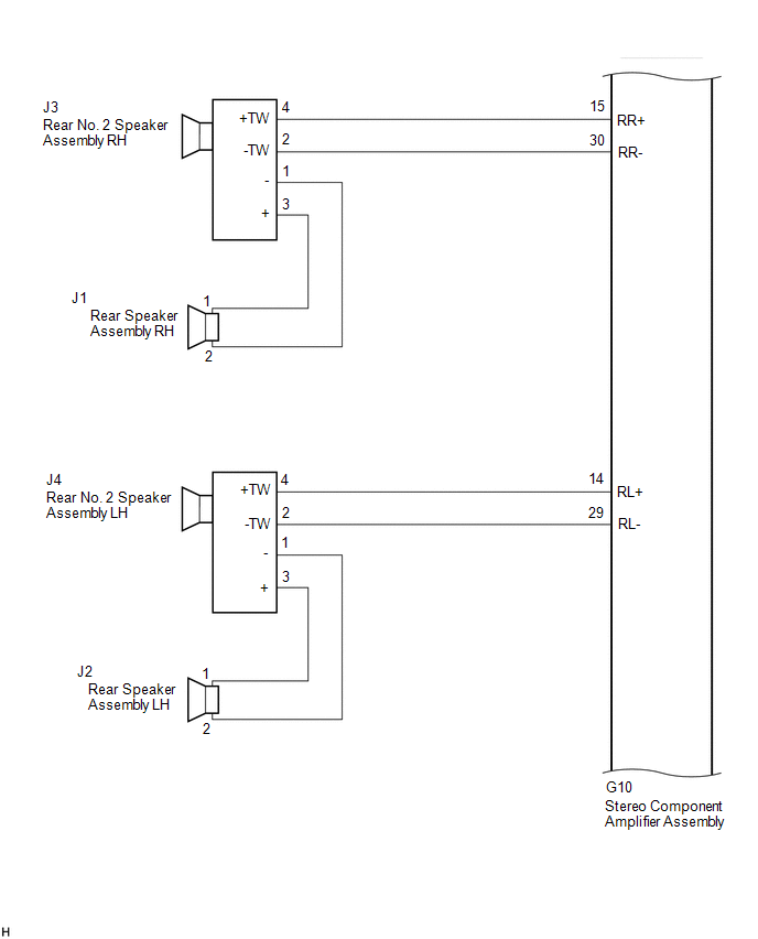
CHECK HARNESS AND CONNECTOR (STEREO COMPONENT AMPLIFIER ASSEMBLY - REAR SPEAKER ASSEMBLY - REAR NO. 2 SPEAKER ASSEMBLY) |
(a) Disconnect the G10 stereo component amplifier assembly connector. (b) Disconnect the J1 and J2 rear speaker assembly connectors.
(c) Disconnect the J3 and J4 rear No. 2 speaker assembly connectors. (d) Measure the resistance according to the value (s) in the table below.
Standard Resistance: |
Tester Connection | Condition |
Specified Condition | |
G10-15 (RR+) - J3-4 (+TW) |
Always | Below 1 Ω | |
G10-30 (RR-) - J3-2 (-TW) |
Always | Below 1 Ω | |
G10-14 (RL+) - J4-4 (+TW) |
Always | Below 1 Ω | |
G10-29 (RL-) - J4-2 (-TW) |
Always | Below 1 Ω | |
J1-1 - J3-3 (+) | Always |
Below 1 Ω | |
J1-2 - J3-1 (-) | Always |
Below 1 Ω | |
J2-1 - J4-3 (+) | Always |
Below 1 Ω | |
J2-2 - J4-1 (-) | Always |
Below 1 Ω | |
G10-15 (RR+) or J3-4 (+TW) - Body ground |
Always | 10 kΩ or higher | |
G10-30 (RR-) or J3-2 (-TW) - Body ground |
Always | 10 kΩ or higher | |
G10-14 (RL+) or J4-4 (+TW) - Body ground |
Always | 10 kΩ or higher | |
G10-29 (RL-) or J4-2 (-TW) - Body ground |
Always | 10 kΩ or higher | |
J1-1 or J3-3 (+) - Body ground |
Always | 10 kΩ or higher | |
J1-2 or J3-1 (-) - Body ground |
Always | 10 kΩ or higher | |
J2-1 or J4-3 (+) - Body ground |
Always | 10 kΩ or higher | |
J2-2 or J4-1 (-) - Body ground |
Always | 10 kΩ or higher |
| NG |
| REPAIR OR REPLACE HARNESS OR CONNECTOR |
|
OK | |
| |
| 14. |
INSPECT REAR SPEAKER ASSEMBLY | (a) Remove the rear speaker assembly.
Click here (b) Inspect the rear speaker assembly.
Click here
| NG |
| REPLACE REAR SPEAKER ASSEMBLY |
|
OK | |
| |
| 15. |
REPLACE REAR NO. 2 SPEAKER ASSEMBLY | (a) Remove the rear No. 2 speaker assembly.
Click here (b) Inspect the rear No. 2 speaker assembly.
Click here OK: Malfunction disappears.
| OK |
| END |
| NG |
| PROCEED TO NEXT SUSPECTED AREA SHOWN IN PROBLEM SYMPTOMS TABLE |
| 16. |
CHECK HARNESS AND CONNECTOR (STEREO COMPONENT AMPLIFIER ASSEMBLY - SPEAKER ASSEMBLY WITH BRACKET) |
(a) Disconnect the G10 stereo component amplifier assembly connector. (b) Disconnect the K2 and K3 speaker assembly with bracket connectors.
(c) Measure the resistance according to the value (s) in the table below.
Standard Resistance: |
Tester Connection | Condition |
Specified Condition | |
G10-11 (SR+) - K2-2 | Always |
Below 1 Ω | |
G10-26 (SR-) - K2-1 | Always |
Below 1 Ω | |
G10-10 (SL+) - K3-2 | Always |
Below 1 Ω | |
G10-25 (SL-) - K3-1 | Always |
Below 1 Ω | |
G10-11 (SR+) or K2-2 - Body ground |
Always | 10 kΩ or higher | |
G10-26 (SR-) or K2-1 - Body ground |
Always | 10 kΩ or higher | |
G10-10 (SL+) or K3-2 - Body ground |
Always | 10 kΩ or higher | |
G10-25 (SL-) or K3-1 - Body ground |
Always | 10 kΩ or higher |
| NG |
| REPAIR OR REPLACE HARNESS OR CONNECTOR |
|
OK | |
| |
| 17. |
INSPECT SPEAKER ASSEMBLY WITH BRACKET |
(a) Remove the speaker assembly with bracket. Click here
(b) Inspect the speaker assembly with bracket.
Click here
| OK |
| PROCEED TO NEXT SUSPECTED AREA SHOWN IN PROBLEM SYMPTOMS TABLE |
| NG |
| REPLACE SPEAKER ASSEMBLY WITH BRACKET |
| 18. |
CHECK HARNESS AND CONNECTOR (STEREO COMPONENT AMPLIFIER ASSEMBLY - REAR NO. 3 SPEAKER ASSEMBLY) |
(a) Disconnect the G10 stereo component amplifier assembly connector. (b) Disconnect the K1 rear No. 3 speaker assembly connector.
(c) Measure the resistance according to the value(s) in the table below.
Standard Resistance: |
Tester Connection | Condition |
Specified Condition | |
G10-6 (WF1+) - K1-4 (WF1+) |
Always | Below 1 Ω | |
G10-21 (WF1-) - K1-3 (WF1-) |
Always | Below 1 Ω | |
G10-5 (WF2+) - K1-2 (WF2+) |
Always | Below 1 Ω | |
G10-20 (WF2-) - K1-1 (WF2-) |
Always | Below 1 Ω | |
G10-6 (WF1+) or K1-4 (WF1+) - Body ground |
Always | 10 kΩ or higher | |
G10-21 (WF1-) or K1-3 (WF1-) - Body ground |
Always | 10 kΩ or higher | |
G10-5 (WF2+) or K1-2 (WF2+) - Body ground |
Always | 10 kΩ or higher | |
G10-20 (WF2-) or K1-1 (WF2-) - Body ground |
Always | 10 kΩ or higher |
| NG |
| REPAIR OR REPLACE HARNESS OR CONNECTOR |
|
OK | |
| |
| 19. |
INSPECT REAR NO. 3 SPEAKER ASSEMBLY | (a) Remove the rear No. 3 speaker assembly.
Click here (b) Inspect the rear No. 3 speaker assembly.
Click here
| OK |
| PROCEED TO NEXT SUSPECTED AREA SHOWN IN PROBLEM SYMPTOMS TABLE |
| NG |
| REPLACE REAR NO. 3 SPEAKER ASSEMBLY | |