DESCRIPTION This circuit consists of the No. 1 clearance warning buzzer and clearance warning ECU assembly. An ECU-excited type buzzer is used. The ECU operates the buzzers using a sound pattern that changes depending on the distance to the obstacle. WIRING DIAGRAM 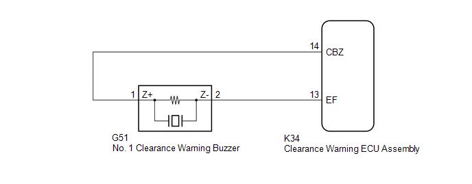 PROCEDURE
(a) Connect the Techstream to the DLC3. (b) Turn the engine switch on (IG). (c) Turn the Techstream on. (d) Enter the following menus: Body Electrical / Advanced Parking Guidance/ICS/Intuitive P/A / Active Test. (e) Check that the front buzzer operates by performing the Active Test. Body Electrical > Advanced Parking Guidance/ICS/Intuitive P/A > Active Test
OK: The No. 1 clearance warning buzzer sounds.
(a) Disconnect the K34 clearance warning ECU assembly connector. (b) Disconnect the G51 No. 1 clearance warning buzzer connector. (c) Measure the resistance according to the value(s) in the table below. Standard Resistance:
(a) Replace the No. 1 clearance warning buzzer with a new or known good one. Click here
(a) Connect the Techstream to the DLC3. (b) Turn the engine switch on (IG). (c) Turn the Techstream on. (d) Enter the following menus: Body Electrical / Advanced Parking Guidance/ICS/Intuitive P/A / Active Test. (e) Check that the front buzzer operates by performing the Active Test. Body Electrical > Advanced Parking Guidance/ICS/Intuitive P/A > Active Test
OK: The No. 1 clearance warning buzzer sounds.
|
Toyota Avalon (XX50) 2019-2022 Service & Repair Manual > Camshaft Oil Control Solenoid: Installation
INSTALLATION PROCEDURE 1. INSTALL CAMSHAFT TIMING OIL CONTROL SOLENOID ASSEMBLY (for Intake Side of Bank 2) (a) Apply engine oil to a new O-ring and install it to the camshaft timing oil control solenoid assembly as shown in the illustration. NOTICE: Do not damage the O-ring. *1 O-ring (b) Apply adh ...


