REMOVAL CAUTION / NOTICE / HINT
The
necessary procedures (adjustment, calibration, initialization or
registration) that must be performed after parts are removed and
installed, or replaced during brake actuator assembly
removal/installation are shown below. Necessary Procedures After Parts Removed/Installed/Replaced |
Replaced Part or Performed Procedure |
Necessary Procedure | Effect/Inoperative Function when Necessary Procedure not Performed |
Link | |
*: When performing learning using the Techstream.
Click here  | |
Battery terminal is disconnected/reconnected |
Perform steering sensor zero point calibration |
Lane departure alert system (w/ Steering Control) |
| |
Pre-collision system | |
Intelligent Clearance Sonar System* | |
Lighting System (for Gasoline Model with Cornering Light) | |
Memorize steering angle neutral point |
Parking assist monitor system |
| |
Panoramic View Monitor System |
| |
Replacement of brake actuator assembly |
Perform system variant learning and acceleration sensor zero point calibration |
- VSC is disabled or malfunctions
- DTCs are output
- Slip indicator light illuminates
- ABS warning light illuminates
|
| |
Operate the electric parking brake switch (electric parking brake switch assembly) |
Parking brake indicator light blinks when the engine switch is first turned on (IG) |
| PROCEDURE
1. PRECAUTION NOTICE: After
turning the engine switch off, waiting time may be required before
disconnecting the cable from the negative (-) battery terminal.
Therefore, make sure to read the disconnecting the cable from the
negative (-) battery terminal notices before proceeding with work. Click here
2. DISCONNECT CABLE FROM NEGATIVE BATTERY TERMINAL
Click here NOTICE: When disconnecting the cable, some systems need to be initialized after the cable is reconnected.
Click here 3. DRAIN BRAKE FLUID
NOTICE: If brake fluid leaks onto any painted surface, immediately wash it off.
4. REMOVE FRONT WHEEL RH Click here
5. REMOVE COWL TOP VENTILATOR LOUVER SUB-ASSEMBLY Click here
6. REMOVE FRONT CENTER UPPER SUSPENSION BRACE SUB-ASSEMBLY
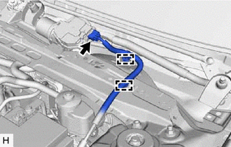
| (a) Disconnect the connector. | |
(b) Disengage the 2 clamps and separate the wire harness.
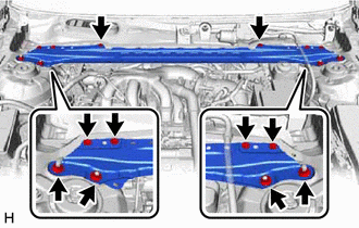
| (c) Remove the 6 bolts, 4 nuts and front center upper suspension brace sub-assembly. |
|
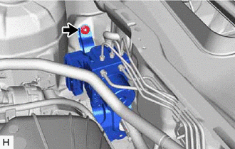
7. REMOVE BRAKE ACTUATOR WITH BRACKET (a) Release the lock lever and disconnect the connector from the brake actuator assembly.
 | Release the lock lever |
 |
Disconnect the connector | NOTICE:
Be careful not to allow any brake fluid to enter the connector.
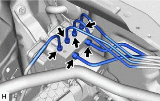
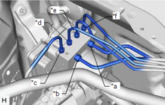
| (b) Use tags or make a memo to identify the places to reconnect the brake lines. |
 |
|
*a | From 1st Chamber of Brake Master Cylinder Sub-assembly | |
*b | From 2nd Chamber of Brake Master Cylinder Sub-assembly | |
*c | To Front Wheel Cylinder Assembly RH | |
*d | To Rear Wheel Cylinder Assembly LH | |
*e | To Rear Wheel Cylinder Assembly RH | |
*f | To Front Wheel Cylinder Assembly LH | | |
| (c) Using a union nut wrench, disconnect the 6 brake lines from the brake actuator assembly.
NOTICE:
- Do not kink or damage the brake lines.
- Do not allow any foreign matter such as dirt or dust to enter the brake lines from the connecting parts.
| |
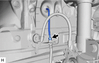
| (d) Using a union nut wrench, disconnect the front No. 3 brake tube while holding the front flexible hose with a wrench.
NOTICE:
- Do not kink or damage the front No. 3 brake tube.
- Do not allow any foreign matter such as dirt or dust to enter the front No. 3 brake tube from the connecting parts.
| |
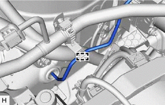
| (e) Disengage the clamp and separate the front No. 3 brake tube.
NOTICE: Do not kink or damage the front No. 3 brake tube. |
|
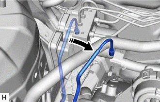
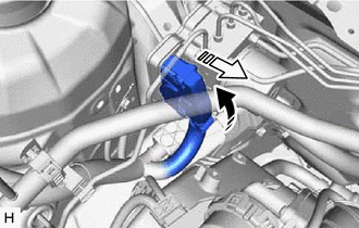
| (f) Move aside the front No. 3 brake tube as shown in the illustration.
NOTICE: Do not apply excessive force to the front No. 3 brake tube. |
|
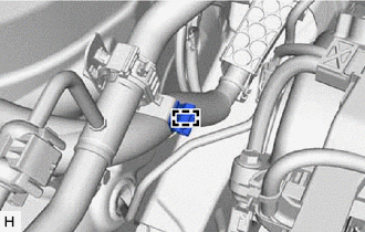
| (g) Disengage the clamp and remove the brake tube clamp. |
|
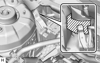
(h) Apply protective tape to the vehicle body as shown in the illustration.
 |
Protective Tape |
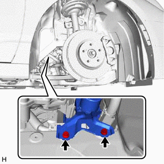
| (i) Remove the 2 bolts. HINT: Insert the tool from the bottom of the vehicle. |
|
| (j) Remove the nut and brake actuator with bracket.
NOTICE:
- Do not kink or damage the brake lines.
- Do not allow any foreign matter such as dirt or dust to enter the brake lines from the connecting parts.
- Be careful not to allow any brake fluid to enter the connector.
- Do not hold the brake actuator assembly by the connector.
- Do not drop the brake actuator with bracket when carrying it.
HINT: Remove the brake actuator with bracket while avoiding the brake lines. |
|
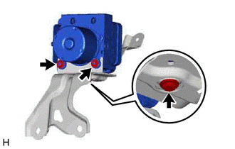
8. REMOVE BRAKE ACTUATOR ASSEMBLY
(b) Remove the bolt and brake actuator assembly from the brake actuator bracket assembly.
NOTICE:
- Do not hold the brake actuator assembly by the connector.
- Do not drop the brake actuator assembly when carrying it.
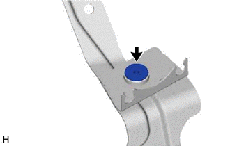
9. REMOVE NO. 1 BRAKE ACTUATOR CASE COLLAR
| (a) Remove the No. 1 brake actuator case collar from the brake actuator bracket cushion. |
|
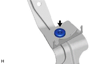
10. REMOVE BRAKE ACTUATOR BOLT CUSHION
| (a) Remove the brake actuator bolt cushion from the brake actuator bracket assembly. |
| |