DESCRIPTION The skid control ECU (brake actuator assembly) receives stop light switch assembly signals and uses them to determine whether or not the brakes are applied. DTCs may be stored if either of the following occurs:
HINT: *: The skid control ECU (brake actuator assembly) may store this DTC upon judging that a stuck on malfunction has occurred when the accelerator pedal and brake pedal are depressed simultaneously. However, this does not indicate a malfunction.
WIRING DIAGRAM 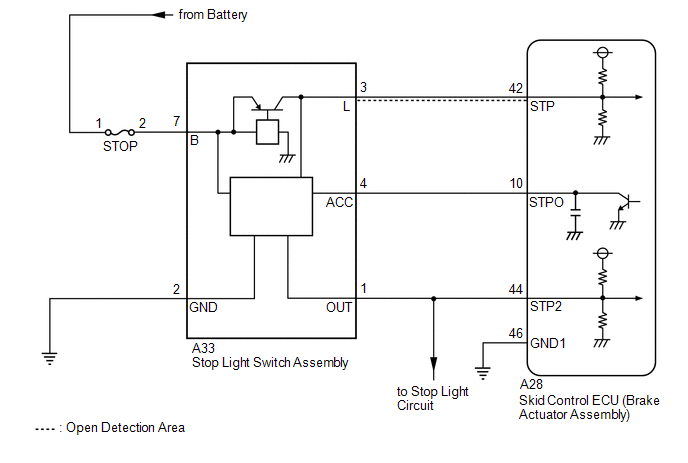 CAUTION / NOTICE / HINT NOTICE:
PROCEDURE
(a) Connect the Techstream to the DLC3. (b) Turn the engine switch on (IG). (c) Enter the following menus: Chassis / ABS/VSC/TRAC/EPB / Data List. Chassis > ABS/VSC/TRAC/EPB > Data List
(d) Take a note of the +BS voltage value. HINT: The noted +BS voltage value is used in a later step.
(a) Interview the customer to check if the pedals were depressed simultaneously while driving or braking. OK: The pedals were not depressed simultaneously. HINT: The skid control ECU (brake actuator assembly) may store this DTC upon judging that a stuck on malfunction has occurred when the accelerator pedal and brake pedal are depressed simultaneously. If the pedals were depressed simultaneously, clear the DTC because it is not a malfunction.
(a) Inspect the stop light switch assembly. Click here OK: The stop light switch assembly is normal.
(a) Connect the Techstream to the DLC3. (b) Turn the engine switch on (IG). (c) Enter the following menus: Chassis / ABS/VSC/TRAC/EPB / Data List. Chassis > ABS/VSC/TRAC/EPB > Data List
(d) Check that the stop light switch assembly display observed on the Techstream changes according to brake pedal operation. OK: The Techstream displays on or off according to brake pedal operation.
(a) Clear the DTCs. Chassis > ABS/VSC/TRAC/EPB > Clear DTCs(b) Turn the engine switch off. (c) Start the engine. (d) Drive the vehicle and depress the brake pedal several times to test the stop light circuit. (e) Check if the same DTC is output. Chassis > ABS/VSC/TRAC/EPB > Trouble Codes
(b) Make sure that there is no looseness at the locking part and the connecting part of the connector. OK: The connector is securely connected. (c) Disconnect the A28 skid control ECU (brake actuator assembly) connector. (d) Check both the connector case and the terminals for deformation and corrosion. OK: No deformation or corrosion. (e) Measure the voltage according to the value(s) in the table below. Standard Voltage:
HINT: *: The minimum voltage value varies depending on the +BS terminal voltage value. The minimum voltage is 85% or more of the +BS terminal voltage.
(a) Clear the DTCs. Chassis > ABS/VSC/TRAC/EPB > Clear DTCs
|
Toyota Avalon (XX50) 2019-2022 Service & Repair Manual > Inverter With Converter: Components
COMPONENTS ILLUSTRATION *1 BATTERY SERVICE HOLE COVER *2 SERVICE PLUG GRIP ILLUSTRATION *1 NO. 1 ENGINE COVER SUB-ASSEMBLY *2 INLET AIR CLEANER ASSEMBLY *3 AIR CLEANER ASSEMBLY WITH AIR CLEANER HOSE *4 COOL AIR INTAKE DUCT SEAL *5 NO. 1 ENGINE UNDER COVER - - N*m (kgf*cm, ft.*lbf): Specified torque ...