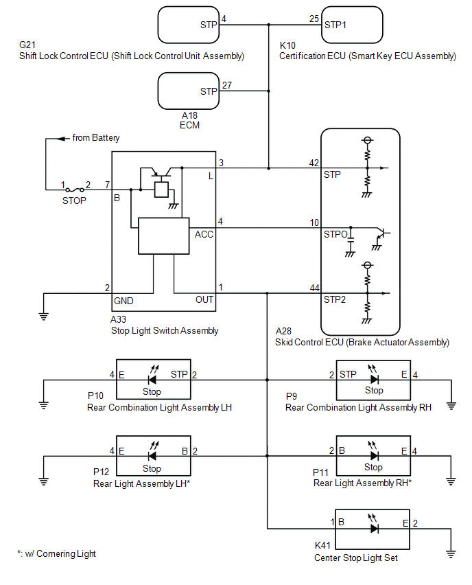
DESCRIPTION When the skid
control ECU (brake actuator assembly) applies the brakes after receiving
a brake request signal from the pre-collision system, dynamic radar
cruise control system, secondary collision brake system or brake hold
control system, the skid control ECU (brake actuator assembly) operates
the stop light control relay (stop light switch assembly) to illuminate
the stop lights. |
DTC No. | Detection Item |
DTC Detection Condition | Trouble Area | |
C1380 | Stop Light Relay Malfunction |
Either condition is met:
- When the voltage at the +BS terminal is between 10 V or more and the
stop light control relay (stop light switch assembly) drive output
(STPO) is on, a signal is not input to the STP terminal for 5 seconds or
more.
- When the voltage at the +BS terminal is between 10 V or more and the
stop light control relay (stop light switch assembly) drive output
(STPO) is off, the signal at the STP2 terminal is different from the
input signal at the STP terminal for 5 seconds or more.
|
- Wire harness or connector
- Stop light switch assembly
- Skid control ECU (brake actuator assembly)
- Rear combination light assembly LH
- Rear light assembly LH*
- Rear combination light assembly RH
- Rear light assembly RH*
- Center stop light set
- Shift lock control ECU (shift lock control unit assembly)
- Certification ECU (smart key ECU assembly)
- ECM
|
DTC Detection Conditions: C1380 | |
Vehicle Condition | |
Pattern 1 | Pattern 2 | |
Diagnosis Condition | The voltage at the +BS terminal is between 10 V or more. |
○ | ○ | |
Malfunction Status | When
the stop light control relay (stop light switch assembly) drive output
(STPO) is on, a signal is not input to the STP terminal. |
○ | - | |
When
the stop light control relay (stop light switch assembly) drive output
(STPO) is off, the signal at the STP2 terminal is different from the
input signal at the STP terminal. |
- | ○ | |
Detection Time | 5 seconds or more |
5 seconds or more | |
Number of Trips | 1 trip |
1 trip | HINT: DTC will be output when conditions for either of the patterns in the table above are met. WIRING DIAGRAM
 CAUTION / NOTICE / HINT
NOTICE:
- When replacing the skid control ECU (brake actuator assembly), perform
system variant learning and acceleration sensor zero point calibration.
Click here 
- Inspect the fuses for circuits related to this system before performing the following procedure.
PROCEDURE |
1. | READ VALUE USING TECHSTREAM (BS1 VOLTAGE VALUE) |
(a) Connect the Techstream to the DLC3. (b) Turn the engine switch on (IG).
(c) Enter the following menus: Chassis / ABS/VSC/TRAC/EPB / Data List. Chassis > ABS/VSC/TRAC/EPB > Data List
|
Tester Display | Measurement Item |
Range | Normal Condition |
Diagnostic Note | |
BS1 Voltage Value | +BS voltage value |
Min.: 0.00 V, Max.: 20.00 V |
- | Changes in proportion to battery voltage | Chassis > ABS/VSC/TRAC/EPB > Data List
|
Tester Display | | BS1 Voltage Value |
(d) Take a note of the +BS voltage value. HINT: The noted +BS voltage value is used in a later step.
|
NEXT |
 | |
| 2. |
CHECK HARNESS AND CONNECTOR (STP2, STPO AND STP TERMINAL) |
| (a) Turn the engine switch off. |
 |
|
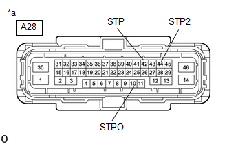
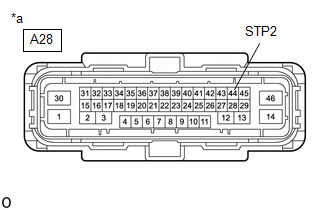
*a | Front view of wire harness connector
(to Skid Control ECU (Brake Actuator Assembly)) | | |
(b) Make sure that there is no looseness at the locking part and the connecting part of the connector.
OK: The connector is securely connected. (c) Disconnect the A28 skid control ECU (brake actuator assembly) connector.
(d) Check both the connector case and the terminals for deformation and corrosion.
OK: No deformation or corrosion. (e) Measure the voltage according to the value(s) in the table below.
Standard Voltage: |
Tester Connection | Condition |
Specified Condition | |
A28-42 (STP) - Body ground |
Stop light switch assembly on (Brake pedal depressed) |
(+BS x 0.85) to 14 V* | |
A28-42 (STP) - Body ground |
Stop light switch assembly off (Brake pedal released) |
Below 1.5 V | |
A28-10 (STPO) - Body ground |
Always | 11 to 14 V | |
A28-44 (STP2) - Body ground |
Stop light switch assembly on (Brake pedal depressed) |
(+BS x 0.85) to 14 V* | |
A28-44 (STP2) - Body ground |
Stop light switch assembly off (Brake pedal released) |
Below 1.5 V | HINT: *:
The minimum voltage value varies depending on the +BS terminal voltage
value. The minimum voltage is 85% or more of the +BS terminal voltage.
|
Result | Proceed to | |
All terminal voltages are normal |
A | | Only STP terminal voltage abnormal |
B | | Only STPO terminal voltage abnormal |
C | | Only STP2 terminal voltage abnormal |
D | | STPO terminal and STP2 terminal voltage abnormal |
E |
| B |
 | GO TO STEP 6 |
| C |
| GO TO STEP 11 |
| D |
| GO TO STEP 12 |
| E |
| GO TO STEP 22 |
|
A | |
| |
| 3. |
PERFORM ACTIVE TEST USING TECHSTREAM (STOP LIGHT RELAY) |
(a) Reconnect the A28 skid control ECU (brake actuator assembly) connector.
(b) Enter the following menus: Chassis / ABS/VSC/TRAC/EPB / Active Test. Chassis > ABS/VSC/TRAC/EPB > Active Test
|
Tester Display | Measurement Item |
Control Range | Diagnostic Note | |
Stop Light Relay | Stop light control relay (Stop light switch assembly) |
Relay OFF/ON | Stop lights come on | Chassis > ABS/VSC/TRAC/EPB > Active Test
|
Tester Display | | Stop Light Relay |
OK: Stop light turns ON/OFF in response to the Techstream operation
| NG |
| GO TO STEP 5 |
|
OK | |
| |
(a) Clear the DTCs. Chassis > ABS/VSC/TRAC/EPB > Clear DTCs
(b) Enter the following menus: Chassis / ABS/VSC/TRAC/EPB / Active Test. Chassis > ABS/VSC/TRAC/EPB > Active Test
|
Tester Display | Measurement Item |
Control Range | Diagnostic Note | |
Stop Light Relay | Stop light control relay (Stop light switch assembly) |
Relay OFF/ON | Stop lights come on | Chassis > ABS/VSC/TRAC/EPB > Active Test
|
Tester Display | | Stop Light Relay |
(c) According to the display on the Techstream, perform the Active Test.
(d) Check if the same DTC is output. Chassis > ABS/VSC/TRAC/EPB > Trouble Codes
|
Result | Proceed to | |
C1380 is output | A | |
C1380 is not output | B |
| A |
| REPLACE BRAKE ACTUATOR ASSEMBLY |
| B |
| USE SIMULATION METHOD TO CHECK |
| 5. |
INSPECT BRAKE ACTUATOR ASSEMBLY | (a) Enter the following menus: Chassis / ABS/VSC/TRAC/EPB / Active Test. Chassis > ABS/VSC/TRAC/EPB > Active Test
|
Tester Display | Measurement Item |
Control Range | Diagnostic Note | |
Stop Light Relay | Stop light control relay (Stop light switch assembly) |
Relay OFF/ON | Stop lights come on | Chassis > ABS/VSC/TRAC/EPB > Active Test
|
Tester Display | | Stop Light Relay |
| (b) Measure the voltage according to the value(s) in the table below.
Standard Voltage: |
Tester Connection | Condition |
Specified Condition | |
A33-4 (ACC) - Body ground |
Active Test is on | Below 1.5 V | |
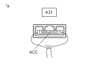 |
|
*a | Component with harness connected
(Stop Light Switch Assembly) | | |
| OK |
| REPLACE STOP LIGHT SWITCH ASSEMBLY |
| NG |
| REPLACE BRAKE ACTUATOR ASSEMBLY |
| 6. |
CHECK HARNESS AND CONNECTOR (BRAKE ACTUATOR ASSEMBLY - SMART KEY ECU ASSEMBLY) |
| (a) Make sure that there is no looseness at the locking part and the connecting part of the connector.
OK: The connector is securely connected. |
 |
|
*a | Front view of wire harness connector
(to Skid Control ECU (Brake Actuator Assembly)) | | |
(b) Disconnect the K10 certification ECU (smart key ECU assembly) connector.
(c) Check both the connector case and the terminals for deformation and corrosion.
OK: No deformation or corrosion. (d) Measure the voltage according to the value(s) in the table below.
Standard Voltage: |
Tester Connection | Condition |
Specified Condition | |
A28-42 (STP) - Body ground |
Stop light switch assembly on (Brake pedal depressed) |
(+BS x 0.85) to 14 V* | |
A28-42 (STP) - Body ground |
Stop light switch assembly off (Brake pedal released) |
Below 1.5 V | HINT: *:
The minimum voltage value varies depending on the +BS terminal voltage
value. The minimum voltage is 85% or more of the +BS terminal voltage.
| OK |
| REPLACE SMART KEY ECU ASSEMBLY |
|
NG | |
| |
| 7. |
CHECK HARNESS AND CONNECTOR (BRAKE ACTUATOR ASSEMBLY - ECM) |
| (a) Make sure that there is no looseness at the locking part and the connecting part of the connector.
OK: The connector is securely connected. | |
|
|
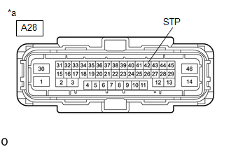
*a | Front view of wire harness connector
(to Skid Control ECU (Brake Actuator Assembly)) | | |
(b) Disconnect the A18 ECM connector. (c) Check both the connector case and the terminals for deformation and corrosion.
OK: No deformation or corrosion. (d) Measure the voltage according to the value(s) in the table below.
Standard Voltage: |
Tester Connection | Condition |
Specified Condition | |
A28-42 (STP) - Body ground |
Stop light switch assembly on (Brake pedal depressed) |
(+BS x 0.85) to 14 V* | |
A28-42 (STP) - Body ground |
Stop light switch assembly off (Brake pedal released) |
Below 1.5 V | HINT: *:
The minimum voltage value varies depending on the +BS terminal voltage
value. The minimum voltage is 85% or more of the +BS terminal voltage.
| OK |
| REPLACE ECM |
|
NG | |
| |
| 8. |
CHECK HARNESS AND CONNECTOR (BRAKE ACTUATOR ASSEMBLY - SHIFT LOCK CONTROL UNIT ASSEMBLY) |
| (a) Make sure that there is no looseness at the locking part and the connecting part of the connector.
OK: The connector is securely connected. | |
|
|
*a | Front view of wire harness connector
(to Skid Control ECU (Brake Actuator Assembly)) | | |
(b) Disconnect the G21 shift lock control ECU (shift lock control unit assembly) connector.
(c) Check both the connector case and the terminals for deformation and corrosion.
OK: No deformation or corrosion. (d) Measure the voltage according to the value(s) in the table below.
Standard Voltage: |
Tester Connection | Condition |
Specified Condition | |
A28-42 (STP) - Body ground |
Stop light switch assembly on (Brake pedal depressed) |
(+BS x 0.85) to 14 V* | |
A28-42 (STP) - Body ground |
Stop light switch assembly off (Brake pedal released) |
Below 1.5 V | HINT: *:
The minimum voltage value varies depending on the +BS terminal voltage
value. The minimum voltage is 85% or more of the +BS terminal voltage.
| OK |
| REPLACE SHIFT LOCK CONTROL UNIT ASSEMBLY |
|
NG | |
| |
| 9. |
CHECK HARNESS AND CONNECTOR (BRAKE ACTUATOR ASSEMBLY - STOP LIGHT SWITCH ASSEMBLY) |
| (a) Make sure that there is no looseness at the locking part and the connecting part of the connector.
OK: The connector is securely connected. | |
|
|
*a | Front view of wire harness connector
(to Skid Control ECU (Brake Actuator Assembly)) | | |
(b) Disconnect the A33 stop light switch assembly connector. (c) Check both the connector case and the terminals for deformation and corrosion.
OK: No deformation or corrosion. (d) Measure the voltage according to the value(s) in the table below.
Standard Voltage: |
Tester Connection | Condition |
Specified Condition | |
A28-42 (STP) - Body ground |
Always | Below 1.5 V |
| NG |
| REPAIR OR REPLACE HARNESS OR CONNECTOR |
|
OK | |
| |
| 10. |
CHECK HARNESS AND CONNECTOR (BRAKE ACTUATOR ASSEMBLY - STOP LIGHT SWITCH ASSEMBLY) |
(a) Measure the resistance according to the value(s) in the table below.
Standard Resistance: |
Tester Connection | Condition |
Specified Condition | |
A28-42 (STP) - A33-3 (L) |
Always | Below 1 Ω | |
A28-42 (STP) or A33-3 (L) - Body ground |
Always | 10 kΩ or higher |
| OK |
| REPLACE STOP LIGHT SWITCH ASSEMBLY |
| NG |
| REPAIR OR REPLACE HARNESS OR CONNECTOR |
| 11. |
CHECK HARNESS AND CONNECTOR (BRAKE ACTUATOR ASSEMBLY - STOP LIGHT SWITCH ASSEMBLY) |
(a) Make sure that there is no looseness at the locking part and the connecting part of the connector.
OK: The connector is securely connected. (b) Disconnect the A33 stop light switch assembly connector.
(c) Check both the connector case and the terminals for deformation and corrosion.
OK: No deformation or corrosion. (d) Measure the resistance according to the value(s) in the table below.
Standard Resistance: |
Tester Connection | Condition |
Specified Condition | |
A28-10 (STPO) - A33-4 (ACC) |
Always | Below 1 Ω |
| OK |
| REPLACE STOP LIGHT SWITCH ASSEMBLY |
| NG |
| REPAIR OR REPLACE HARNESS OR CONNECTOR |
| 12. |
CHECK HARNESS AND CONNECTOR (BRAKE ACTUATOR ASSEMBLY - REAR COMBINATION LIGHT ASSEMBLY LH) |
| (a) Make sure that there is no looseness at the locking part and the connecting part of the connector.
OK: The connector is securely connected. |
 |
|
*a | Front view of wire harness connector
(to Skid Control ECU (Brake Actuator Assembly)) | | |
(b) Disconnect the P10 rear combination light assembly LH connector. (c) Check both the connector case and the terminals for deformation and corrosion.
OK: No deformation or corrosion. (d) Measure the voltage according to the value(s) in the table below.
Standard Voltage: |
Tester Connection | Condition |
Specified Condition | |
A28-44 (STP2) - Body ground |
Stop light switch assembly on (Brake pedal depressed) |
(+BS x 0.85) to 14 V* | |
A28-44 (STP2) - Body ground |
Stop light switch assembly off (Brake pedal released) |
Below 1.5 V | HINT: *:
The minimum voltage value varies depending on the +BS terminal voltage
value. The minimum voltage is 85% or more of the +BS terminal voltage.
| OK |
| REPLACE REAR COMBINATION LIGHT ASSEMBLY LH |
|
NG | |
| |
| 13. |
CHECK HARNESS AND CONNECTOR (BRAKE ACTUATOR ASSEMBLY - REAR COMBINATION LIGHT ASSEMBLY RH) |
| (a) Make sure that there is no looseness at the locking part and the connecting part of the connector.
OK: The connector is securely connected. | |
|
|
*a | Front view of wire harness connector
(to Skid Control ECU (Brake Actuator Assembly)) | | |
(b) Disconnect the P9 rear combination light assembly RH connector. (c) Check both the connector case and the terminals for deformation and corrosion.
OK: No deformation or corrosion. (d) Measure the voltage according to the value(s) in the table below.
Standard Voltage: |
Tester Connection | Condition |
Specified Condition | |
A28-44 (STP2) - Body ground |
Stop light switch assembly on (Brake pedal depressed) |
(+BS x 0.85) to 14 V* | |
A28-44 (STP2) - Body ground |
Stop light switch assembly off (Brake pedal released) |
Below 1.5 V | HINT: *:
The minimum voltage value varies depending on the +BS terminal voltage
value. The minimum voltage is 85% or more of the +BS terminal voltage.
|
Result | Proceed to | |
OK | A | |
NG (w/o Cornering Light) | B | |
NG (w/ Cornering Light) |
C |
| A |
| REPLACE REAR COMBINATION LIGHT ASSEMBLY RH |
| C |
| GO TO STEP 17 |
|
B | |
| |
| 14. |
CHECK HARNESS AND CONNECTOR (BRAKE ACTUATOR ASSEMBLY - CENTER STOP LIGHT SET) |
| (a) Make sure that there is no looseness at the locking part and the connecting part of the connector.
OK: The connector is securely connected. | |
|
|
*a | Front view of wire harness connector
(to Skid Control ECU (Brake Actuator Assembly)) | | |
(b) Disconnect the K41 center stop light set connector. (c) Check both the connector case and the terminals for deformation and corrosion.
OK: No deformation or corrosion. (d) Measure the voltage according to the value(s) in the table below.
Standard Voltage: |
Tester Connection | Condition |
Specified Condition | |
A28-44 (STP2) - Body ground |
Stop light switch assembly on (Brake pedal depressed) |
(+BS x 0.85) to 14 V* | |
A28-44 (STP2) - Body ground |
Stop light switch assembly off (Brake pedal released) |
Below 1.5 V | HINT: *:
The minimum voltage value varies depending on the +BS terminal voltage
value. The minimum voltage is 85% or more of the +BS terminal voltage.
| OK |
| REPLACE CENTER STOP LIGHT SET |
|
NG | |
| |
| 15. |
CHECK HARNESS AND CONNECTOR (BRAKE ACTUATOR ASSEMBLY - STOP LIGHT SWITCH ASSEMBLY) |
| (a) Make sure that there is no looseness at the locking part and the connecting part of the connector.
OK: The connector is securely connected. | |
|
|
*a | Front view of wire harness connector
(to Skid Control ECU (Brake Actuator Assembly)) | | |
(b) Disconnect the A33 stop light switch assembly connector. (c) Check both the connector case and the terminals for deformation and corrosion.
OK: No deformation or corrosion. (d) Measure the voltage according to the value(s) in the table below.
Standard Voltage: |
Tester Connection | Condition |
Specified Condition | |
A28-44 (STP2) - Body ground |
Always | Below 1.5 V |
| NG |
| REPAIR OR REPLACE HARNESS OR CONNECTOR |
|
OK | |
| |
| 16. |
CHECK HARNESS AND CONNECTOR (BRAKE ACTUATOR ASSEMBLY - STOP LIGHT SWITCH ASSEMBLY) |
(a) Measure the resistance according to the value(s) in the table below.
Standard Resistance: |
Tester Connection | Condition |
Specified Condition | |
A33-1 (OUT) - A28-44 (STP2) |
Always | Below 1 Ω | |
A33-1 (OUT) or A28-44 (STP2) - Body ground |
Always | 10 kΩ or higher |
| OK |
| REPLACE STOP LIGHT SWITCH ASSEMBLY |
| NG |
| REPAIR OR REPLACE HARNESS OR CONNECTOR |
| 17. |
CHECK HARNESS AND CONNECTOR (BRAKE ACTUATOR ASSEMBLY - REAR LIGHT ASSEMBLY LH) |
| (a) Make sure that there is no looseness at the locking part and the connecting part of the connector.
OK: The connector is securely connected. | |
|
|
*a | Front view of wire harness connector
(to Skid Control ECU (Brake Actuator Assembly)) | | |
(b) Disconnect the P12 rear light assembly LH connector. (c) Check both the connector case and the terminals for deformation and corrosion.
OK: No deformation or corrosion. (d) Measure the voltage according to the value(s) in the table below.
Standard Voltage: |
Tester Connection | Condition |
Specified Condition | |
A28-44 (STP2) - Body ground |
Stop light switch assembly on (Brake pedal depressed) |
(+BS x 0.85) to 14 V* | |
A28-44 (STP2) - Body ground |
Stop light switch assembly off (Brake pedal released) |
Below 1.5 V | HINT: *:
The minimum voltage value varies depending on the +BS terminal voltage
value. The minimum voltage is 85% or more of the +BS terminal voltage.
| OK |
| REPLACE REAR LIGHT ASSEMBLY LH |
|
NG | |
| |
| 18. |
CHECK HARNESS AND CONNECTOR (BRAKE ACTUATOR ASSEMBLY - REAR LIGHT ASSEMBLY RH) |
| (a) Make sure that there is no looseness at the locking part and the connecting part of the connector.
OK: The connector is securely connected. | |
|
|
*a | Front view of wire harness connector
(to Skid Control ECU (Brake Actuator Assembly)) | | |
(b) Disconnect the P11 rear light assembly RH connector. (c) Check both the connector case and the terminals for deformation and corrosion.
OK: No deformation or corrosion. (d) Measure the voltage according to the value(s) in the table below.
Standard Voltage: |
Tester Connection | Condition |
Specified Condition | |
A28-44 (STP2) - Body ground |
Stop light switch assembly on (Brake pedal depressed) |
(+BS x 0.85) to 14 V* | |
A28-44 (STP2) - Body ground |
Stop light switch assembly off (Brake pedal released) |
Below 1.5 V | HINT: *:
The minimum voltage value varies depending on the +BS terminal voltage
value. The minimum voltage is 85% or more of the +BS terminal voltage.
| OK |
| REPLACE REAR LIGHT ASSEMBLY RH |
|
NG | |
| |
| 19. |
CHECK HARNESS AND CONNECTOR (BRAKE ACTUATOR ASSEMBLY - CENTER STOP LIGHT SET) |
| (a) Make sure that there is no looseness at the locking part and the connecting part of the connector.
OK: The connector is securely connected. | |
|
|
*a | Front view of wire harness connector
(to Skid Control ECU (Brake Actuator Assembly)) | | |
(b) Disconnect the K41 center stop light set connector. (c) Check both the connector case and the terminals for deformation and corrosion.
OK: No deformation or corrosion. (d) Measure the voltage according to the value(s) in the table below.
Standard Voltage: |
Tester Connection | Condition |
Specified Condition | |
A28-44 (STP2) - Body ground |
Stop light switch assembly on (Brake pedal depressed) |
(+BS x 0.85) to 14 V* | |
A28-44 (STP2) - Body ground |
Stop light switch assembly off (Brake pedal released) |
Below 1.5 V | HINT: *:
The minimum voltage value varies depending on the +BS terminal voltage
value. The minimum voltage is 85% or more of the +BS terminal voltage.
| OK |
| REPLACE CENTER STOP LIGHT SET |
|
NG | |
| |
| 20. |
CHECK HARNESS AND CONNECTOR (BRAKE ACTUATOR ASSEMBLY - STOP LIGHT SWITCH ASSEMBLY) |
| (a) Make sure that there is no looseness at the locking part and the connecting part of the connector.
OK: The connector is securely connected. | |
|
|
*a | Front view of wire harness connector
(to Skid Control ECU (Brake Actuator Assembly)) | | |
(b) Disconnect the A33 stop light switch assembly connector. (c) Check both the connector case and the terminals for deformation and corrosion.
OK: No deformation or corrosion. (d) Measure the voltage according to the value(s) in the table below.
Standard Voltage: |
Tester Connection | Condition |
Specified Condition | |
A28-44 (STP2) - Body ground |
Always | Below 1.5 V |
| NG |
| REPAIR OR REPLACE HARNESS OR CONNECTOR |
|
OK | |
| |
| 21. |
CHECK HARNESS AND CONNECTOR (BRAKE ACTUATOR ASSEMBLY - STOP LIGHT SWITCH ASSEMBLY) |
(a) Measure the resistance according to the value(s) in the table below.
Standard Resistance: |
Tester Connection | Condition |
Specified Condition | |
A33-1 (OUT) - A28-44 (STP2) |
Always | Below 1 Ω | |
A33-1 (OUT) or A28-44 (STP2) - Body ground |
Always | 10 kΩ or higher |
| OK |
| REPLACE STOP LIGHT SWITCH ASSEMBLY |
| NG |
| REPAIR OR REPLACE HARNESS OR CONNECTOR |
| 22. |
CHECK STOP LIGHT SWITCH ASSEMBLY POWER SOURCE CIRCUIT |
| (a) Make sure that there is no looseness at the locking part and the connecting part of the connector.
OK: The connector is securely connected. |
 |
|
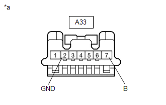
*a | Front view of wire harness connector
(to Stop Light Switch Assembly) | | |
(b) Disconnect the A33 stop light switch assembly connector. (c) Check both the connector case and the terminals for deformation and corrosion.
OK: No deformation or corrosion. (d) Measure the resistance according to the value(s) in the table below.
Standard Resistance: |
Tester Connection | Condition |
Specified Condition | |
A33-2 (GND) - Body ground |
Always | Below 1 Ω |
(e) Measure the voltage according to the value(s) in the table below. Standard Voltage: |
Tester Connection | Condition |
Specified Condition | |
A33-7 (B) - Body ground |
Always | 11 to 14 V |
| NG |
| REPAIR OR REPLACE HARNESS OR CONNECTOR |
|
OK | |
| |
| 23. |
CHECK HARNESS AND CONNECTOR (BRAKE ACTUATOR ASSEMBLY - STOP LIGHT SWITCH ASSEMBLY) |
(a) Measure the resistance according to the value(s) in the table below.
Standard Resistance: |
Tester Connection | Condition |
Specified Condition | |
A28-10 (STPO) or A33-4 (ACC) - Body ground |
Always | 10 kΩ or higher |
| OK |
| REPLACE STOP LIGHT SWITCH ASSEMBLY |
| NG |
| REPAIR OR REPLACE HARNESS OR CONNECTOR | | 

