DESCRIPTION The skid control ECU (brake actuator assembly) receives stop light switch assembly signals and uses them to determine whether or not the brakes are applied. The skid control ECU (brake actuator assembly) has a detection circuit that it uses to detect a short in the stop light input signal circuit or stop light circuit when the stop light switch assembly is on (brake pedal depressed). If the skid control ECU (brake actuator assembly) detects a short in this circuit, it will store this DTC.
HINT: DTC will be output when conditions for either of the patterns in the table above are met. WIRING DIAGRAM Refer to DTC C1249. Click here CAUTION / NOTICE / HINT NOTICE:
PROCEDURE
(a) Connect the Techstream to the DLC3. (b) Turn the engine switch on (IG). (c) Enter the following menus: Chassis / ABS/VSC/TRAC/EPB / Data List. Chassis > ABS/VSC/TRAC/EPB > Data List
(d) Take a note of the +BS voltage value. HINT: The noted +BS voltage value is used in a later step.
(a) Check the brake pedal height installation. Click here
(b) Check the stop light switch assembly installation. Click here OK: The brake pedal height and stop light switch assembly installation are normal. HINT: If the on/off status of the stop light switch assembly and pressure increase information from the master cylinder pressure sensor do not match due to an improperly installed brake pedal or stop light switch assembly, this DTC may be stored. Therefore, be sure to check the installation condition of the pedal and switch before inspecting the input signals and other related parts.
(a) Check that the stop lights come on when the brake pedal is depressed, and go off when the brake pedal is released. OK:
(a) Inspect the stop light switch assembly. Click here OK: The stop light switch assembly is normal.
(a) Connect the Techstream to the DLC3. (b) Turn the engine switch on (IG). (c) Enter the following menus: Chassis / ABS/VSC/TRAC/EPB / Data List. Chassis > ABS/VSC/TRAC/EPB > Data List
(d) Check that the stop light switch assembly display observed on the Techstream changes according to brake pedal operation. OK: The Techstream displays on or off according to brake pedal operation.
(a) Clear the DTCs. Chassis > ABS/VSC/TRAC/EPB > Clear DTCs(b) Turn the engine switch off. (c) Start the engine. (d) Drive the vehicle at a speed of 3 km/h (2 mph) or more and depress the brake pedal several times to test the stop light circuit. (e) Check if the same DTC is output. Chassis > ABS/VSC/TRAC/EPB > Trouble Codes
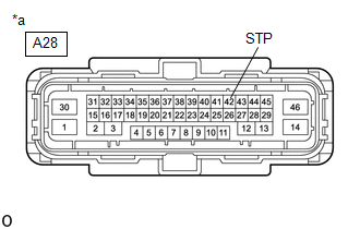
(b) Make sure that there is no looseness at the locking part and the connecting part of the connector. OK: The connector is securely connected. (c) Disconnect the A28 skid control ECU (brake actuator assembly) connector. (d) Check both the connector case and the terminals for deformation and corrosion. OK: No deformation or corrosion. (e) Measure the voltage according to the value(s) in the table below. Standard Voltage:
HINT: *: The minimum voltage value varies depending on the +BS terminal voltage value. The minimum voltage is 85% or more of the +BS terminal voltage.
(a) Inspect the stop light switch assembly. Click here OK: The stop light switch assembly is normal.
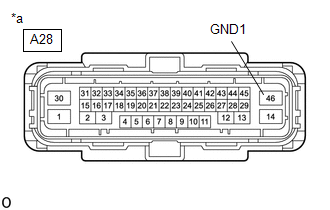
(b) Disconnect the A28 skid control ECU (brake actuator assembly) connector. (c) Check both the connector case and the terminals for deformation and corrosion. OK: No deformation or corrosion. (d) Measure the voltage according to the value(s) in the table below. Standard Voltage:
HINT: *: The minimum voltage value varies depending on the +BS terminal voltage value. The minimum voltage is 85% or more of the +BS terminal voltage.
(a) Reconnect the A28 skid control ECU (brake actuator assembly) connector. (b) Clear the DTCs. Chassis > ABS/VSC/TRAC/EPB > Clear DTCs(c) Turn the engine switch off. (d) Start the engine. (e) Drive the vehicle at a speed of 3 km/h (2 mph) or more and depress the brake pedal several times to test the stop light circuit. (f) Check if the same DTC is output. Chassis > ABS/VSC/TRAC/EPB > Trouble Codes
HINT: If the lighting system is normal but the DTC is still output, replace the skid control ECU (brake actuator assembly). Click here
| ||||||||||||||||||||||||||||||||||||||||||||||||||||||||||||||||||||||||||||||||||||||||||||||||||||||||||||||||||||||||||||||||||||||||||||||||||||||||||||||||||||||||||||||||||||||||||||||||||||||||||
Toyota Avalon (XX50) 2019-2022 Service & Repair Manual > Audio / Video: Microphone
ComponentsCOMPONENTS ILLUSTRATION *A for Normal Roof *B for Moon Roof *1 ROOF CONSOLE BOX ASSEMBLY *2 TELEPHONE MICROPHONE ASSEMBLY *3 ROOF CONSOLE BOX SUB-ASSEMBLY - - InstallationINSTALLATION PROCEDURE 1. INSTALL TELEPHONE MICROPHONE ASSEMBLY (a) for Normal Roof: (1) Engage the 2 claws to install ...