DESCRIPTION
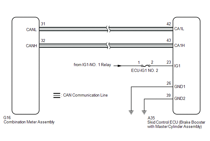
The skid control ECU (brake booster with master cylinder assembly) is connected to the combination meter assembly via CAN communication.
CAUTION / NOTICE / HINT
NOTICE:
After replacing the skid control ECU (brake booster with master cylinder assembly), perform linear solenoid valve offset learning, ABS holding solenoid valve learning, yaw rate and acceleration sensor zero point calibration and system information memorization after performing "Reset Memory".
Click here 
PROCEDURE
| 1. |
CHECK CAN COMMUNICATION SYSTEM |
(a) Check if CAN communication system DTCs are output.
Click here
|
Result | Proceed to |
|---|---|
|
DTCs are not output. |
A |
| DTCs are output. |
B |
| B |
 | INSPECT CAN COMMUNICATION SYSTEM |
|
| 2. |
PERFORM ACTIVE TEST USING TECHSTREAM (ABS WARNING LIGHT) |
(a) Select the Active Test on the Techstream.
Click here
|
Tester Display | Measurement Item |
Control Range | Diagnostic Note |
|---|---|---|---|
|
ABS Warning Light | ABS warning light |
Warning light ON/OFF | Observe combination meter assembly |
|
Tester Display | Measurement Item |
Range | Normal Condition |
Diagnostic Note |
|---|---|---|---|---|
|
ABS Warning Light | ABS warning light |
ON or OFF | ON: Warning light on OFF: Warning light off |
- |
|
Active Test Display |
|---|
|
ABS Warning Light |
|
Data List Display |
|---|
|
ABS Warning Light |
(b) Check the operating condition of the ABS warning light when operating it using the Techstream.
| Result |
Proceed to |
|---|---|
| ABS warning light in the Data List does not change using the Active Test. |
A |
| ABS warning light in the Data List turns ON/OFF using the Active Test. |
B |
| A |
| REPLACE BRAKE BOOSTER WITH MASTER CYLINDER ASSEMBLY |
|
| 3. |
INSPECT COMBINATION METER ASSEMBLY |
(a) Perform the Active Test of the combination meter assembly (meter CPU) using the Techstream.
Click here
|
Tester Display |
|---|
| ABS Warning |
(b) Check the combination meter assembly.
OK:
The ABS warning light turns on or off in accordance with Techstream operation.
| OK | | REPLACE BRAKE BOOSTER WITH MASTER CYLINDER ASSEMBLY |
| NG | | INSPECT METER / GAUGE SYSTEM |
DESCRIPTION
The skid control ECU (brake booster with master cylinder assembly) is connected to the combination meter assembly via CAN communication.
If any of the following is detected, the ABS warning light remains on:
HINT:
In some cases, the Techstream cannot be used when the skid control ECU (brake booster with master cylinder assembly) is malfunctioning.
WIRING DIAGRAM
CAUTION / NOTICE / HINT
NOTICE:
Click here 
PROCEDURE
|
1. | CHECK CAN COMMUNICATION SYSTEM |
(a) Check if CAN communication system DTCs are output.
Click here
|
Result | Proceed to |
|---|---|
|
DTCs are not output. |
A |
| DTCs are output. |
B |
| B |
 | INSPECT CAN COMMUNICATION SYSTEM |
|
| 2. |
CHECK IF BRAKE BOOSTER WITH MASTER CYLINDER ASSEMBLY CONNECTOR IS SECURELY CONNECTED |
(a) Check if the skid control ECU (brake booster with master cylinder assembly) connector is securely connected.
OK:
The connector is securely connected.
| NG | | CONNECT CONNECTOR TO BRAKE BOOSTER WITH MASTER CYLINDER ASSEMBLY CORRECTLY |
|
| 3. |
CHECK AUXILIARY BATTERY |
(a) Check the auxiliary battery voltage.
Standard Voltage:
|
Tester Connection | Condition |
Specified Condition |
|---|---|---|
|
Auxiliary battery | Power switch on (IG) |
11 to 14 V |
|
Auxiliary battery | Power switch on (READY) |
11 to 15.5 V |
| NG | | CHARGE OR REPLACE AUXILIARY BATTERY |
|
| 4. |
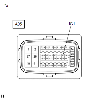
CHECK HARNESS AND CONNECTOR (IG1 TERMINAL) |
| (a) Turn the power switch off. |
|
(b) Make sure that there is no looseness at the locking part and the connecting part of the connector.
OK:
The connector is securely connected.
(c) Disconnect the A35 skid control ECU (brake booster with master cylinder assembly) connector.
(d) Check both the connector case and the terminals for deformation and corrosion.
OK:
No deformation or corrosion.
(e) Turn the power switch on (IG).
(f) Measure the voltage according to the value(s) in the table below.
Standard Voltage:
|
Tester Connection | Condition |
Specified Condition |
|---|---|---|
|
A35-23 (IG1) - Body ground |
Power switch on (IG) |
11 to 14 V |
| NG | | REPAIR OR REPLACE HARNESS OR CONNECTOR (IG1 CIRCUIT) |
|
| 5. |
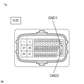
CHECK HARNESS AND CONNECTOR (GND TERMINAL) |
| (a) Turn the power switch off. |
|
(b) Measure the resistance according to the value(s) in the table below.
Standard Resistance:
|
Tester Connection | Condition |
Specified Condition |
|---|---|---|
|
A35-26 (GND1) - Body ground |
Always | Below 1 Ω |
|
A35-39 (GND2) - Body ground |
Always | Below 1 Ω |
| NG | | REPAIR OR REPLACE HARNESS OR CONNECTOR (GND CIRCUIT) |
|
| 6. |
READ VALUE USING TECHSTREAM (ABS WARNING LIGHT) |
(a) Reconnect the A35 skid control ECU (brake booster with master cylinder assembly) connector.
(b) Select the Data List on the Techstream.
Click here
|
Tester Display | Measurement Item |
Range | Normal Condition |
Diagnostic Note |
|---|---|---|---|---|
|
ABS Warning Light | ABS warning light |
ON or OFF | ON: Warning light on OFF: Warning light off |
- |
|
Tester Display |
|---|
| ABS Warning Light |
(c) Check the Techstream display condition of the ABS warning light.
| Result |
Proceed to |
|---|---|
| ON is displayed. |
A |
| OFF is displayed. |
B |
| A |
| REPLACE BRAKE BOOSTER WITH MASTER CYLINDER ASSEMBLY |
| B |
| INSPECT METER / GAUGE SYSTEM |
CAUTION / NOTICE / HINT
NOTICE:
After replacing the brake actuator assembly, perform linear solenoid valve offset learning, ABS holding solenoid valve learning, yaw rate and acceleration sensor zero point calibration and system information memorization after performing "Reset Memory".
Click here

PROCEDURE
| 1. |
PERFORM ROAD TEST |
(a) After turning the power switch on (READY), compare the operating sound of the brake actuator the first time the vehicle speed reaches approximately 25 km/h (16 mph) with a known good vehicle of the same model.
OK:
The operating sound is the same or quieter than that of a known good vehicle of the same model.
HINT:
When the vehicle speed reaches approximately 20 km/h (12 mph), the initial check of the brake actuator assembly is performed and pump motor operation sounds are generated.
| OK |  |
END |
|
| 2. |
CHECK BRAKE ACTUATOR BOLT CUSHION |
(a) Check that the cushion of the brake actuator bracket assembly is not worn, damaged or deformed.
OK:
The brake actuator bracket assembly is not worn, damaged or deformed.
| NG | | REPLACE BRAKE ACTUATOR BOLT CUSHION |
|
| 3. |
ADJUST INSTALLATION OF BRAKE ACTUATOR ASSEMBLY |
(a) Drain the brake fluid.
(b) Disconnect all brake lines from the brake actuator assembly.
Click here
(c) Connect each brake line so that the cushion of the brake actuator assembly is tensioned evenly.
Click here
NOTICE:
After connecting all the brake lines, add brake fluid and bleed the brake system.
Click here
HINT:
By reducing the tension on the brake lines and cushion, the operating sound of the brake actuator assembly may be reduced.
(d) Check that no brake lines interfere the vehicle body or other components.
|
| 4. |
RECHECK SYMPTOM |
(a) Perform a road test and check the magnitude of the operating sound again.
OK:
The operating sound is the same or quieter than that of a known good vehicle of the same model.
| OK | | END |
| NG | | REPLACE BRAKE ACTUATOR ASSEMBLY |
Toyota Avalon (XX50) 2019-2022 Owners Manual > Specifications: Fuel information
You must only use unleaded gasoline. Select octane rating 87 (Research Octane Number 91) or higher. Use of unleaded gasoline with an octane rating lower than 87 may result in engine knocking. Persistent knocking can lead to engine damage. At minimum, the gasoline you use should meet the specificati ...