DESCRIPTION
If a malfunction is detected in the power source circuit, the skid control ECU (brake booster with master cylinder assembly) stores DTC C1417 and prohibits operation of ABS, brake assist, regenerative brake cooperative control, etc.
DTC C1417 is stored if an excessive ECU voltage due to a malfunction in the auxiliary battery, charging circuit, etc. is detected, and is cleared when the ECU voltage returns to normal.
|
DTC No. | Detection Item |
INF Code | DTC Detection Condition |
Trouble Area | MIL |
Note |
|---|---|---|---|---|---|---|
| C1417 |
IG1 Voltage Supply too High |
553 | The internal voltage of the skid control ECU (brake booster with master cylinder assembly) is 16.44 V or more for 0.8 seconds or more. |
| Comes on |
|
| C14DF |
Brake Pressure Control Solenoid Supply Voltage Circuit High |
- | The power source voltage of the linear solenoid is 16 V or more for 0.8 seconds or more. |
| Comes on |
- |
MONITOR DESCRIPTION
When the vehicle is being driven, if the voltage at VM1, IG1 or BS is a specific value or more due to a malfunction in the auxiliary battery and hybrid control system (charging circuit), the skid control ECU (brake booster with master cylinder assembly) judges that there is an increase in the power supply voltage of VM1, IG1 or BS and illuminates the MIL and stores a DTC.
MONITOR STRATEGY
|
Related DTCs | C1417 (Case 1): Brake system voltage circuit high C1417 (Case 2): Brake system voltage circuit high C14DF: Main relay voltage circuit high |
|
Required Sensors/Components(Main) | Skid control ECU (brake booster with master cylinder assembly) |
|
Required Sensors/Components(Related) | Speed sensor |
|
Frequency of Operation | Continuous |
|
Duration | 0.8 seconds |
| MIL Operation |
Immediately |
| Sequence of Operation |
None |
TYPICAL ENABLING CONDITIONS
All|
Monitor runs whenever the following DTCs are not stored |
None |
|
Vehicle speed | Higher than 3 km/h (2 mph) |
TYPICAL MALFUNCTION THRESHOLDS
C1417 (Case 1)|
IG1 voltage | 17.4 V or more |
|
Brake system voltage 1 (VM1) | 16.44 V or more |
|
Power supply for linear solenoid | 16 V or more |
COMPONENT OPERATING RANGE
C1417 (Case 1)|
Both of the following conditions are met |
- |
| Vehicle speed |
Higher than 3 km/h (2 mph) |
|
IG1 voltage | Less than 17.4 V, and 3.5 V or more |
|
Both of the following conditions are met |
- |
| Control valve solenoid | Non-drive |
|
Brake system voltage 1 (VM1) | Less than 16.44 V |
|
Both of the following conditions are met |
- |
| Main relay | On |
|
Power supply for linear solenoid | Less than 16 V |
CONFIRMATION DRIVING PATTERN
HINT:
Click here 
HINT:
WIRING DIAGRAM
Refer to DTC C1241.
Click here
CAUTION / NOTICE / HINT
NOTICE:
Click here
PROCEDURE
|
1. | CHECK AUXILIARY BATTERY |
(a) Check the auxiliary battery voltage.
Standard Voltage:
|
Tester Connection | Condition |
Specified Condition |
|---|---|---|
|
Auxiliary battery | Power switch on (IG) |
11 to 14 V |
|
Auxiliary battery | Power switch on (READY) |
11 to 15.5 V |
| NG |  | CHARGE OR REPLACE AUXILIARY BATTERY |
|
| 2. |
CHECK HARNESS AND CONNECTOR (POWER SOURCE TERMINAL) |
| (a) Turn the power switch off. |
|
(b) Make sure that there is no looseness at the locking part and the connecting part of the connector.
OK:
The connector is securely connected.
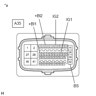
(c) Disconnect the A35 skid control ECU (brake booster with master cylinder assembly) connector.
(d) Check both the connector case and the terminals for deformation and corrosion.
OK:
No deformation or corrosion.
(e) Measure the voltage according to the value(s) in the table below.
Standard Voltage:
|
Tester Connection | Condition |
Specified Condition |
|---|---|---|
|
A35-15 (+BI1) - Body ground |
Always | 11 to 14 V |
|
A35-5 (+BI2) - Body ground |
Always | 11 to 14 V |
|
A35-52 (BS) - Body ground |
Always | 11 to 14 V |
|
A35-23 (IG1) - Body ground |
Power switch on (IG) |
11 to 14 V |
|
A35-9 (IG2) - Body ground |
Power switch on (IG) |
11 to 14 V |
| NG | | REPAIR OR REPLACE HARNESS OR CONNECTOR (POWER SOURCE CIRCUIT) |
|
| 3. |
RECONFIRM DTC |
(a) Turn the power switch off.
(b) Reconnect the A35 skid control ECU (brake booster with master cylinder assembly) connector.
(c) Clear the DTCs.
Click here
(d) Turn the power switch off.
(e) Turn the power switch on (READY).
(f) Perform a road test.
(g) Check if the same DTC is output.
Click here
| Result |
Proceed to |
|---|---|
| DTCs C1417 and C14DF are not output. |
A |
| DTCs C1417 and/or C14DF are output. |
B |
| A |
| USE SIMULATION METHOD TO CHECK |
| B |
| REPLACE BRAKE BOOSTER WITH MASTER CYLINDER ASSEMBLY |
DESCRIPTION
The airbag ECU assembly has a built-in yaw rate and acceleration sensor and detects the vehicle condition using 2 circuits (GL1, GL2).
If an internal malfunction signal from the yaw rate and acceleration sensor (airbag ECU assembly) is detected by the skid control ECU (brake booster with master cylinder assembly), DTC C1419 and/or DTC C1435 is stored.
|
DTC No. | Detection Item |
INF Code | DTC Detection Condition |
Trouble Area | MIL |
Note |
|---|---|---|---|---|---|---|
| C1419 |
Deceleration Sensor Internal Circuit |
1137 | Acceleration sensor internal malfunction signal is detected. |
Acceleration sensor (airbag ECU assembly) |
Comes on |
|
| C1435 |
Yaw Rate Sensor Internal Circuit |
711 712 | Yaw rate sensor internal malfunction signal is detected. |
Yaw rate sensor (airbag ECU assembly) |
Does not come on | VSC DTC |
MONITOR DESCRIPTION
C0520 (Case 3):MONITOR STRATEGY
C0520 (Case 3)|
Related DTCs | C0520 (Case 3): Acceleration sensor internal malfunction |
|
Required Sensors/Components(Main) | Acceleration sensor (airbag ECU assembly) |
|
Required Sensors/Components(Related) | Skid control ECU (brake booster with master cylinder assembly) |
|
Frequency of Operation | Continuous |
|
Duration | - |
| MIL Operation |
Immediately |
| Sequence of Operation |
None |
TYPICAL ENABLING CONDITIONS
C0520 (Case 3)|
Monitor runs whenever the following DTCs are not stored |
None |
| Lost communication with yaw rate and acceleration sensor (airbag ECU assembly) |
Not detected |
TYPICAL MALFUNCTION THRESHOLDS
C0520 (Case 3)|
Either of the following conditions is met | - |
|
Acceleration sensor 1 (longitudinal G) error (CAN communication data) |
"1" (abnormality) |
| Acceleration sensor 2 (lateral G) error (CAN communication data) |
"1" (abnormality) |
COMPONENT OPERATING RANGE
C0520 (Case 3)|
All of the following conditions are met | - |
|
Lost communication with yaw rate and acceleration sensor (airbag ECU assembly) |
Not detected |
| Yaw rate and acceleration sensor power supply voltage (IG) invalidation/validation (CAN communication data) |
"0" (valid) |
| Acceleration sensor 1 (longitudinal G) error (CAN communication data) |
"0" (no abnormality) |
| Acceleration sensor 2 (lateral G) error (CAN communication data) |
"0" (no abnormality) |
CONFIRMATION DRIVING PATTERN
HINT:
Click here 
HINT:
CAUTION / NOTICE / HINT
NOTICE:
After replacing or reinstalling the yaw rate and acceleration sensor (airbag ECU assembly), perform yaw rate and acceleration sensor zero point calibration after clearing previously calibrated data.
Click here
PROCEDURE
| 1. |
REPLACE AIRBAG ECU ASSEMBLY |
(a) Replace the yaw rate and acceleration sensor (airbag ECU assembly).
Click here
| NEXT |  | END |
DESCRIPTION
The airbag ECU assembly has a built-in yaw rate and acceleration sensor and detects the vehicle condition using 2 circuits (GL1, GL2).
The skid control ECU (brake booster with master cylinder assembly) receives signals from the yaw rate and acceleration sensor (airbag ECU assembly) via CAN communication.
|
DTC No. | Detection Item |
INF Code | DTC Detection Condition |
Trouble Area | MIL |
Note |
|---|---|---|---|---|---|---|
| C1420 |
Malfunction in Deceleration Sensor |
571 | After the difference between GL1 and GL2 is 0.6 G or more with the vehicle stopped, the difference between GL1 and GL2 does not drop below 0.4 G or more for 60 seconds or more. |
| Does not come on |
ABS DTC |
CAUTION / NOTICE / HINT
NOTICE:
After replacing or reinstalling the yaw rate and acceleration sensor (airbag ECU assembly), perform yaw rate and acceleration sensor zero point calibration after clearing previously calibrated data.
Click here

PROCEDURE
| 1. |
CHECK AIRBAG ECU ASSEMBLY INSTALLATION |
(a) Check that the yaw rate and acceleration sensor (airbag ECU assembly) has been installed properly.
Click here
OK:
The yaw rate and acceleration sensor (airbag ECU assembly) is tightened to the specified torque.
The yaw rate and acceleration sensor (airbag ECU assembly) is not tilted.
| OK |  | REPLACE AIRBAG ECU ASSEMBLY |
| NG | | INSTALL AIRBAG ECU ASSEMBLY CORRECTLY |
Toyota Avalon (XX50) 2019-2022 Service & Repair Manual > 2gr-fks Fuel: Fuel Pressure Sensor
Components COMPONENTS ILLUSTRATION *1 FUEL PRESSURE SENSOR (FUEL DELIVERY PIPE WITH SENSOR ASSEMBLY) - - Inspection INSPECTION PROCEDURE 1. INSPECT FUEL PRESSURE SENSOR (FUEL DELIVERY PIPE WITH SENSOR ASSEMBLY) NOTICE: Do not remove the fuel pressure sensor from the fuel delivery pipe with sensor as ...