COMPONENTS
ILLUSTRATION
|
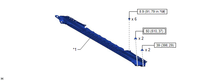
*1 | FRONT CENTER UPPER SUSPENSION BRACE SUB-ASSEMBLY |
- | - |
 |
Tightening torque for "Major areas involving basic vehicle performance such as moving/turning/stopping": N*m (kgf*cm, ft.*lbf) |
 |
N*m (kgf*cm, ft.*lbf): Specified torque |
ILLUSTRATION
|
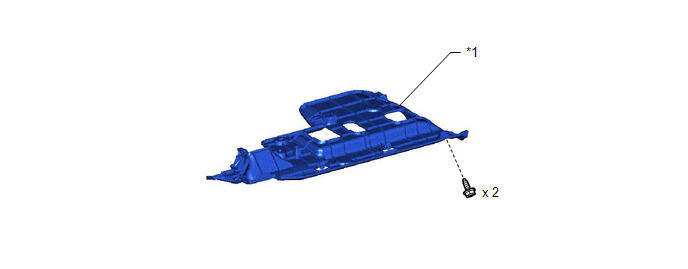
*1 | NO. 1 INSTRUMENT PANEL UNDER COVER SUB-ASSEMBLY |
- | - |
ILLUSTRATION
|
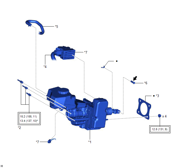
*1 | BRAKE BOOSTER WITH MASTER CYLINDER ASSEMBLY |
*2 | BRAKE LINE |
|
*3 | BRAKE MASTER CYLINDER GASKET |
*4 | ENGINE ROOM MAIN WIRE |
|
*5 | NO. 1 BRAKE ACTUATOR HOSE |
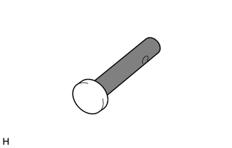
*6 | PUSH ROD PIN |
|
*7 | CONNECTOR |
- | - |
|
|
Tightening torque for "Major areas involving basic vehicle performance such as moving/turning/stopping": N*m (kgf*cm, ft.*lbf) |
* | For use with a union nut wrench |
|
● | Non-reusable part |
 |
Lithium soap base glycol grease |
INSTALLATION
PROCEDURE
1. INSTALL BRAKE MASTER CYLINDER GASKET
(a) Install a new brake master cylinder gasket to the brake booster with master cylinder assembly.
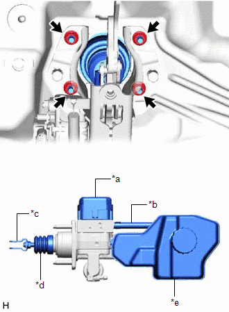
2. INSTALL BRAKE BOOSTER WITH MASTER CYLINDER ASSEMBLY
| (a) Install the brake booster with master cylinder assembly with the 4 nuts. Torque: 12.8 N·m {131 kgf·cm, 9 ft·lbf} NOTICE:
|
|
3. INSTALL PUSH ROD PIN
(a) Apply lithium soap base glycol grease to the push rod pin.
 | Lithium Soap Base Glycol Grease |
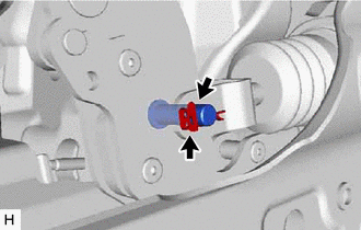
| (b) Connect the brake master cylinder push rod clevis to the brake pedal support assembly with the push rod pin, and install a new clip as shown in the illustration. HINT: The push rod pin can be installed in either direction. |
|
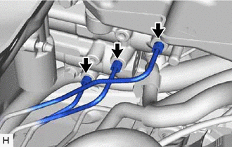
4. CONNECT BRAKE LINE
|
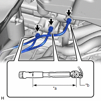
(a) Using a union nut wrench, connect the 3 brake lines to the brake booster with master cylinder assembly. Torque: Specified tightening torque : 15.2 N·m {155 kgf·cm, 11 ft·lbf} NOTICE:
HINT:
|
|
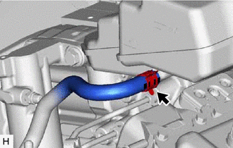
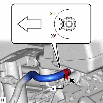
5. CONNECT NO. 1 BRAKE ACTUATOR HOSE
(a) Connect the No. 1 brake actuator hose to the brake booster with master cylinder assembly and slide the clip to secure it.
|
*a | Identification Mark |
 |
Front of the vehicle |
NOTICE:
6. CONNECT ENGINE ROOM MAIN WIRE
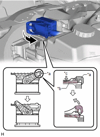
(a) Connect the connector to the brake booster with master cylinder assembly and lock the lock lever as shown in the illustration.
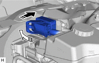
 | Connect the connector |
 | Lock the lock lever |
NOTICE:
| (b) Connect the connector to the brake booster with master cylinder assembly. |
|
7. BLEED NO. 1 BRAKE ACTUATOR TUBE
NOTICE:
Make sure to bleed the air from the No. 1 brake actuator tube. If the air remains in the No. 1 brake actuator tube, the air will enter the brake booster pump assembly and may damage the brake booster pump assembly.
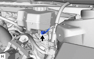
(a) Remove the brake master cylinder reservoir filler cap assembly.
(b) Add brake fluid to the reservoir until the fluid level is between the MAX and MIN lines on the brake fluid reservoir.
Brake Fluid:
SAE J1703 or FMVSS No. 116 DOT3
SAE J1704 or FMVSS No. 116 DOT4
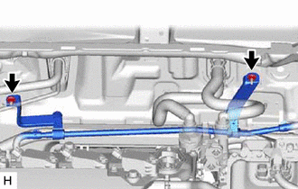
| (c) Remove the 2 nuts to separate the No. 1 brake actuator tube. |
|
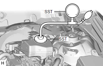
| (d) Set SST to the brake master cylinder reservoir assembly. SST: 09992-00242 SST: 09992-00350 |
|
(e) Using SST, increase and then maintain the pressure in the brake master cylinder reservoir assembly for 60 seconds.(*1)
Standard Pressure:
50 to 80 kPa (0.6 to 0.8 kgf/cm2, 7.3 to 11.6 psi)
(f) Release the pressure in the brake master cylinder reservoir assembly and wait for 30 seconds.(*2)
(g) Repeat steps *1 to *2, 3 times.
(h) Remove SST.
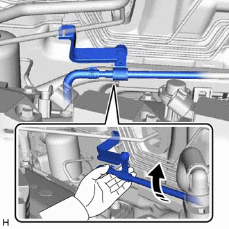
(i) Elevate the No. 1 brake actuator tube for 10 seconds by lifting the No. 1 brake actuator tube as shown in the illustration.(*3)
|
| Pull up |
NOTICE:
Do not damage the hoses by applying excessive force.
(j) Repeat step *3, 5 times.
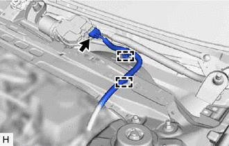
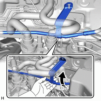
(k) Elevate the No. 1 brake actuator tube for 10 seconds by lifting the No. 1 brake actuator tube as shown in the illustration.(*4)
NOTICE:
Do not damage the hoses by applying excessive force.
|
| Pull up |
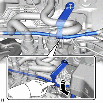
(l) Lower the No. 1 brake actuator tube for 10 seconds as shown in the illustration.(*5)
NOTICE:
Do not damage the hoses by applying excessive force.
|
| Press down |
(m) Repeat steps *4 to *5, 5 times.
(n) Install the No. 1 brake actuator tube with the 2 nuts.
Torque:
8.5 N·m {87 kgf·cm, 75 in·lbf}
8. CONNECT BRAKE BOOSTER PUMP CONNECTOR
HINT:
Perform this operation only when the accumulator pressure zero down operation could not be performed using the Techstream.
(a) Connect the connector to the brake booster pump assembly and lock the lock lever as shown in the illustration.
|
| Connect the connector |
|
| Lock the lock lever |
NOTICE:
9. FILL RESERVOIR WITH BRAKE FLUID
10. CONNECT CABLE TO NEGATIVE AUXILIARY BATTERY TERMINAL
Click here 
11. BLEED BRAKE SYSTEM
Click here
12. INSPECT AND ADJUST BRAKE PEDAL
Click here
13. OBTAIN ZERO POINT OF YAW RATE AND ACCELERATION SENSOR
Click here
14. INSTALL NO. 1 INSTRUMENT PANEL UNDER COVER SUB-ASSEMBLY
Click here
15. INSTALL FRONT CENTER UPPER SUSPENSION BRACE SUB-ASSEMBLY
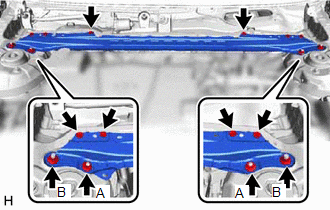
| (a) Temporarily install the front center upper suspension brace sub-assembly with the 6 bolts and 4 nuts. |
|
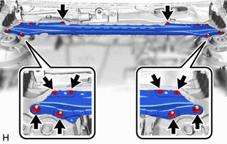
(b) Fully tighten the 2 nuts (A).
Torque:
50 N·m {510 kgf·cm, 37 ft·lbf}
(c) Fully tighten the 6 bolts and 2 nuts (B) to install the front center upper suspension brace sub-assembly.
Torque:
Bolt :
8.9 N·m {91 kgf·cm, 79 in·lbf}
Nut (B) :
39 N·m {398 kgf·cm, 29 ft·lbf}
(d) Engage the 2 clamps to install the wire harness.
(e) Connect the connector.
16. INSTALL COWL TOP VENTILATOR LOUVER SUB-ASSEMBLY
Click here
REMOVAL
CAUTION / NOTICE / HINT
The necessary procedures (adjustment, calibration, initialization, or registration) that must be performed after parts are removed, installed, or replaced during brake booster with master cylinder assembly removal/installation are shown below.
Necessary Procedures After Parts Removed/Installed/Replaced|
Replaced Part or Performed Procedure |
Necessary Procedure | Effect/Inoperative Function when Necessary Procedure not Performed |
Link |
|---|---|---|---|
| Auxiliary battery terminal is disconnected/reconnected |
Perform steering sensor zero point calibration |
Lane Departure Alert System (w/ Steering Control) |
|
|
Pre-collision System | |||
|
Intelligent Clearance Sonar System* | |||
|
Lighting System (for HV Model with Cornering Light) | |||
|
Memorize steering angle neutral point |
Parking Assist Monitor System |
| |
|
Panoramic View Monitor System |
| ||
|
Replacement of brake booster with master cylinder assembly |
|
| for Initialization
for Calibration:
|
|
NOTICE:
While the auxiliary battery is connected, even if the power switch is off, the brake control system activates when the brake pedal is depressed or any door courtesy switch turns on. Therefore, when servicing the brake system components, do not operate the brake pedal or open/close the doors while the auxiliary battery is connected.
PROCEDURE
1. PRECAUTION
NOTICE:
After turning the power switch off, waiting time may be required before disconnecting the cable from the negative (-) auxiliary battery terminal. Therefore, make sure to read the disconnecting the cable from the negative (-) auxiliary battery terminal notices before proceeding with work.
Click here 
2. PERFORM ACCUMULATOR PRESSURE ZERO DOWN
(a) Using the Techstream, perform the accumulator pressure zero down operation.
(1) Connect the Techstream to the DLC3 with the power switch off.
(2) Turn the power switch on (IG).
(3) Turn the Techstream on and enter the following menus: Chassis / ABS/VSC/TRAC / Utility / ECB (Electronically Controlled Brake system) Utility.
Chassis > ABS/VSC/TRAC > Utility|
Tester Display |
|---|
| ECB Utility |
(4) Select "Motor Invalid" on the "ECB (Electronically Controlled Brake system) Utility" screen.
(5) Perform "Motor Invalid" according to the display on the Techstream.
(6) Enter the following menus: Chassis / ABS/VSC/TRAC / Utility / ECB (Electronically Controlled Brake system) Utility.
Chassis > ABS/VSC/TRAC > Utility|
Tester Display |
|---|
| ECB Utility |
(7) Select "ECB (Electronically Controlled Brake system) Invalid" on the "ECB (Electronically Controlled Brake system) Utility" screen.
(8) Perform "ECB (Electronically Controlled Brake system) Invalid" according to the display on the Techstream.
(9) Depress the brake pedal 40 times or more to return all the fluid in the accumulator back to the reservoir.
HINT:
A buzzer may sound due to low accumulator pressure. As this is not a malfunction, continue the procedure.
(10) Check that the brake pedal is firm.
NOTICE:
If the brake pedal is not firm or the pump motor continues to operate even after depressing the brake pedal 40 times or more, the accumulator pressure zero down operation is not complete.
(11) Turn the Techstream off and turn the power switch off.
(12) Disconnect the Techstream from the DLC3.
(13) Disconnect the cable from the negative (-) auxiliary battery terminal.
Click here
(b) When the accumulator pressure zero down could not be performed using the Techstream.
NOTICE:
If DTCs are output, the accumulator pressure zero down operation may not be complete. In this case, perform the following procedure.
(1) With the power switch off, release the lock lever and disconnect the brake booster pump assembly connector as shown in the illustration.
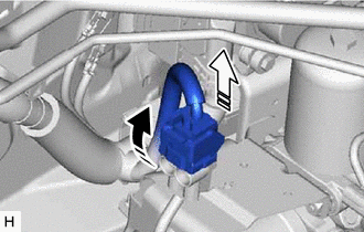
 | Release the lock lever |
 |
Disconnect the connector |
NOTICE:
Be careful not to allow any brake fluid to enter the connector.
(2) Depress the brake pedal 40 times or more to return all the fluid in the accumulator back to the reservoir.
(3) Check that the brake pedal is firm.
NOTICE:
If the brake pedal is not firm or the pump motor continues to operate even after depressing the brake pedal 40 times or more, the accumulator pressure zero down operation is not complete.
(4) Disconnect the cable from the negative (-) auxiliary battery terminal.
Click here
3. REMOVE COWL TOP VENTILATOR LOUVER SUB-ASSEMBLY
Click here
4. REMOVE FRONT CENTER UPPER SUSPENSION BRACE SUB-ASSEMBLY
| (a) Disconnect the connector. |
|
(b) Disengage the 2 clamps and separate the wire harness.
| (c) Remove the 6 bolts, 4 nuts and front center upper suspension brace sub-assembly. |
|
5. DRAIN BRAKE FLUID
NOTICE:
If brake fluid leaks onto any painted surface, immediately wash it off.
6. DISCONNECT ENGINE ROOM MAIN WIRE
| (a) Disconnect the connector from the brake booster with master cylinder assembly. |
|
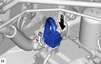
(b) Push the lock arm of the connector to disengage the lock and release the lock lever as shown in the illustration.
|
*a | Lock Lever |
|
*b | Lock Arm |
|
*c | Push |
|
|
Release the lock lever |
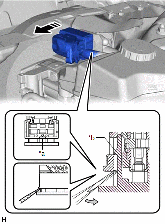
(c) Using a screwdriver, release the pre-lock and disconnect the connector from the brake booster with master cylinder assembly as shown in the illustration.
|
*a | Screwdriver Insertion Point |
|
*b | Pre-lock |
|
|
Disconnect the connector |
NOTICE:
Be careful not to allow any brake fluid to enter the connector.
7. DISCONNECT NO. 1 BRAKE ACTUATOR HOSE
| (a) Slide the clip and disconnect the No. 1 brake actuator hose from the brake booster with master cylinder assembly. |
|
8. DISCONNECT BRAKE LINE
|
(a) Using a union nut wrench, disconnect the 3 brake lines from the brake booster with master cylinder assembly. NOTICE:
|
|
9. REMOVE NO. 1 INSTRUMENT PANEL UNDER COVER SUB-ASSEMBLY
Click here
10. REMOVE PUSH ROD PIN
| (a) Remove the clip and push rod pin. |
|
11. REMOVE BRAKE BOOSTER WITH MASTER CYLINDER ASSEMBLY
| (a) Remove the 4 nuts and brake booster with master cylinder assembly. NOTICE:
|
|
12. REMOVE BRAKE MASTER CYLINDER GASKET
Toyota Avalon (XX50) 2019-2022 Service & Repair Manual > Rear Suspension: Rear Stabilizer Bar
Components COMPONENTS ILLUSTRATION *A for Gasoline Model - - *1 NO. 1 FLOOR UNDER COVER *2 NO. 2 FLOOR UNDER COVER N*m (kgf*cm, ft.*lbf): Specified torque - - ILLUSTRATION *1 REAR NO. 1 STABILIZER BAR BRACKET LH *2 REAR NO. 1 STABILIZER BAR BRACKET RH *3 REAR STABILIZER BAR *4 REAR STABILIZER BUSHIN ...