PRECAUTION
TROUBLESHOOTING PRECAUTION
NOTICE:
DISCONNECTING AND CONNECTING FLEXIBLE HOSE AND BRAKE LINE
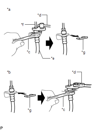
(a) Disconnecting:
|
*a | Disconnecting |
|
*b | Connecting |
|
*c | Hold |
|
*d | Turn |
|
*e | Flexible Hose |
|
*f | Brake Line |
|
*g | Clip |
(1) Hold the flexible hose with a wrench and disconnect the brake line using a union nut wrench without deforming the brake line.
(2) Remove the clip and disconnect the flexible hose.
(b) Connecting:
(1) Secure the flexible hose with a new clip. Be sure to securely install the clip.
(2) Connect the brake line using a union nut wrench without deforming the brake line.
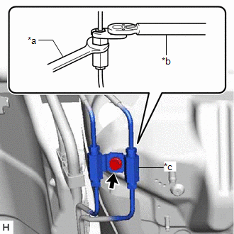
CONNECTING BRAKE LINE AND WAY
(a) While supporting the way to prevent deformation of the brake line, connect the brake line to the way with a union nut wrench.
|
*a | Hold |
|
*b | Turn |
|
*c | Way |
(b) While supporting the way to prevent deformation of the brake line, install the bolt to secure the way to the vehicle body.
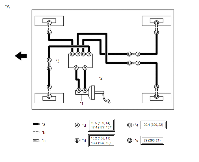
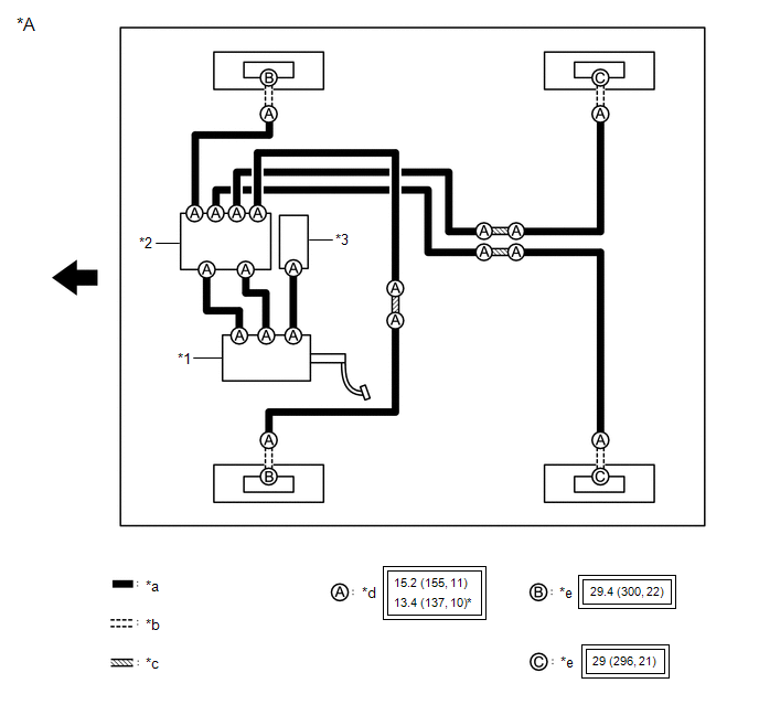
SYSTEM DIAGRAM
HINT:
See the layout drawing to confirm the locations and tightening torque of flexible hoses and brake lines.
|
*A | for Gasoline Model |
- | - |
|
*1 | Brake Master Cylinder Sub-assembly |
*2 | Brake Booster Assembly |
|
*3 | Brake Actuator Assembly |
- | - |
|
*a | Brake Line |
*b | Flexible Hose |
|
*c | Brake Tube Way |
*d | Union Nut |
|
*e | Union Bolt |
- | - |
 |
Tightening torque for "Major areas involving basic vehicle performance such as moving/turning/stopping" : N*m (kgf*cm, ft.*lbf) |
* | For use with a union nut wrench |
 |
Front | - |
- |
|
*A | for HV Model |
- | - |
|
*1 | Brake Booster with Master Cylinder Assembly |
*2 | Brake Actuator Assembly |
|
*3 | Brake Booster Pump Assembly |
- | - |
|
*a | Brake Line |
*b | Flexible Hose |
|
*c | Brake Tube Way |
*d | Union Nut |
|
*e | Union Bolt |
- | - |
|
|
Tightening torque for "Major areas involving basic vehicle performance such as moving/turning/stopping": N*m (kgf*cm, ft.*lbf) |
* | For use with a union nut wrench |
|
|
Front | - |
- |
Toyota Avalon (XX50) 2019-2022 Service & Repair Manual > Automatic Transaxle System: Pressure Control Solenoid "H" Circuit Short to Ground or Open (P281614). Parts Location. Precaution
Pressure Control Solenoid "H" Circuit Short to Ground or Open (P281614) DESCRIPTION Refer to DTC P281612. Click here DTC No. Detection Item DTC Detection Condition Trouble Area MIL Memory Note P281614 Pressure Control Solenoid "H" Circuit Short to Ground or Open While the vehicle is being driven so ...

