COMPONENTS
ILLUSTRATION
|
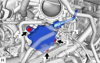
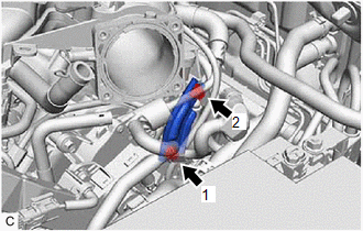
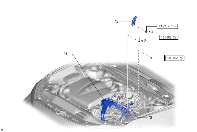
*1 | ENGINE WIRE |
*2 | NO. 2 SURGE TANK STAY |
|
*3 | EARTH WIRE |
- | - |
 |
Tightening torque for "Major areas involving basic vehicle performance such as moving/turning/stopping" : N*m (kgf*cm, ft.*lbf) |
 | N*m (kgf*cm, ft.*lbf): Specified torque |
ILLUSTRATION
|
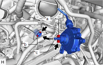
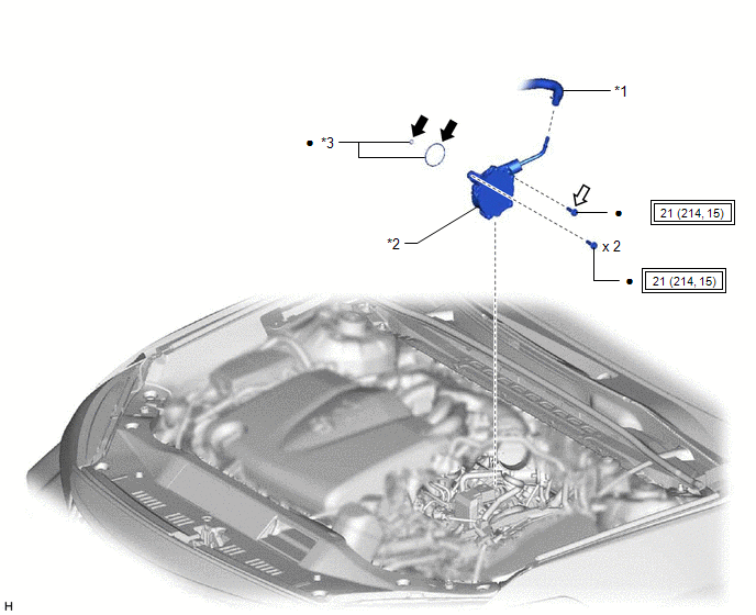
*1 | AIR TUBE |
*2 | VACUUM PUMP ASSEMBLY |
|
*3 | O-RING |
- | - |
|
|
Tightening torque for "Major areas involving basic vehicle performance such as moving/turning/stopping" : N*m (kgf*cm, ft.*lbf) |
● | Non-reusable part |
 |
Engine oil |
 |
Adhesive 1324 |
|
★ | Precoated part |
- | - |
INSTALLATION
PROCEDURE
1. INSTALL VACUUM PUMP ASSEMBLY
(a) When using a new vacuum pump assembly:
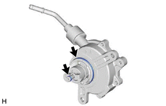
(1) Apply engine oil to the 2 O-rings which are installed to a new vacuum pump assembly.
 | Engine oil |
(b) When reusing the vacuum pump assembly:
(1) Apply engine oil to 2 new O-rings and install them to the vacuum pump assembly.
|
| Engine oil |
(c) Apply engine oil to the inner surface of the installation hole.
| (d) Temporarily install the vacuum pump assembly so that the oil pipe engages with the hole of the camshaft and the coupling teeth engages with the groove of the camshaft. NOTICE:
|
|
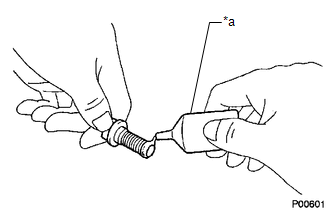
| (e) Apply adhesive to 3 or more threads at the tip of 1 of 3 new bolts. Adhesive: Toyota Genuine Adhesive 1324, Three Bond 1324 or equivalent |
|
| (f) Install the vacuum pump assembly with the 3 bolts. Torque: 21 N·m {214 kgf·cm, 15 ft·lbf} NOTICE:
|
|
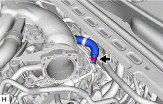
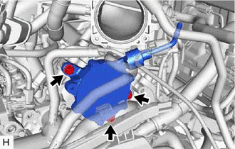
2. CONNECT AIR TUBE
| (a) Connect the air tube to the vacuum pump assembly, and slide the clip to secure it. |
|
3. INSTALL ENGINE WIRE
|
(a) Install the earth wire with the bolt. Torque: 10 N·m {102 kgf·cm, 7 ft·lbf} |
|
| (b) Install the engine wire with the 2 bolts. Torque: 10 N·m {102 kgf·cm, 7 ft·lbf} |
|
4. INSTALL NO. 2 SURGE TANK STAY
| (a) Install the No. 2 surge tank stay with the 2 bolts in the order shown in the illustration. Torque: 21 N·m {214 kgf·cm, 15 ft·lbf} |
|
5. INSTALL THROTTLE BODY WITH MOTOR ASSEMBLY
Click here

6. INSPECT VACUUM PUMP OPERATION
Click here
ON-VEHICLE INSPECTION
PROCEDURE
1. REMOVE COWL TOP VENTILATOR LOUVER SUB-ASSEMBLY
Click here

2. REMOVE FRONT CENTER UPPER SUSPENSION BRACE SUB-ASSEMBLY
Click here
3. OPERATION CHECK
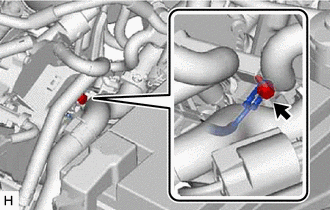
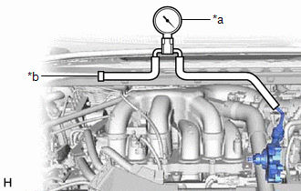
(a) Slide the clip and disconnect the air tube from the vacuum pump assembly.
| (b) Connect the hose of the vacuum gauge to the vacuum pump assembly. |
|
(c) Start the engine and warm it up for more than 2 minutes.
(d) With the engine idling, check the vacuum of the vacuum pump assembly.
Standard Pressure:
More than 86.7 kPa (650 mmHg, 25.6 in.Hg)
HINT:
If the result is not as specified, replace the vacuum pump assembly.
(e) Remove the vacuum gauge from the vacuum pump assembly.
(f) Connect the air tube to the vacuum pump assembly, and slide the clip to secure it.
4. INSTALL FRONT CENTER UPPER SUSPENSION BRACE SUB-ASSEMBLY
Click here
5. INSTALL COWL TOP VENTILATOR LOUVER SUB-ASSEMBLY
Click here
REMOVAL
PROCEDURE
1. REMOVE THROTTLE BODY WITH MOTOR ASSEMBLY
Click here 
2. REMOVE NO. 2 SURGE TANK STAY
Click here
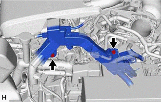
3. SEPARATE ENGINE WIRE
| (a) Remove the 2 bolts and separate the engine wire. |
|
| (b) Remove the bolt and separate the earth wire. |
|
4. DISCONNECT AIR TUBE
|
(a) Slide the clip and disconnect the air tube from the vacuum pump assembly. |
|
5. REMOVE VACUUM PUMP ASSEMBLY
| (a) Remove the 3 bolts and vacuum pump assembly from the engine assembly. |
|
| (b) Remove the 2 O-rings from the vacuum pump assembly. |
|
Toyota Avalon (XX50) 2019-2022 Owners Manual > Opening, closing and
locking the doors: Smart key system
The following operations can be performed simply by carrying the electronic key on your person, for example in your pocket. The driver should always carry the electronic key. Locks and unlocks the doors Opens the trunk Starts the engine ■Antenna location Antennas outside the cabin Antennas inside ...