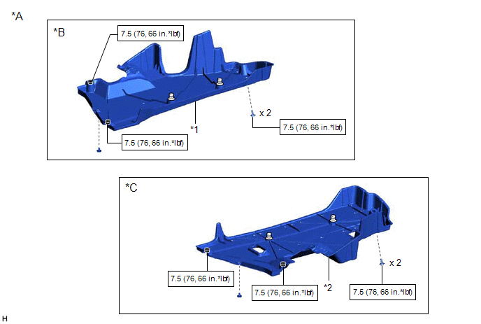
COMPONENTS
ILLUSTRATION
|
*A | for Gasoline Model |
*B | for RH Side |
|
*C | for LH Side |
- | - |
|
*1 | NO. 1 FLOOR UNDER COVER |
*2 | NO. 2 FLOOR UNDER COVER |
 |
N*m (kgf*cm, ft.*lbf): Specified torque |
- | - |
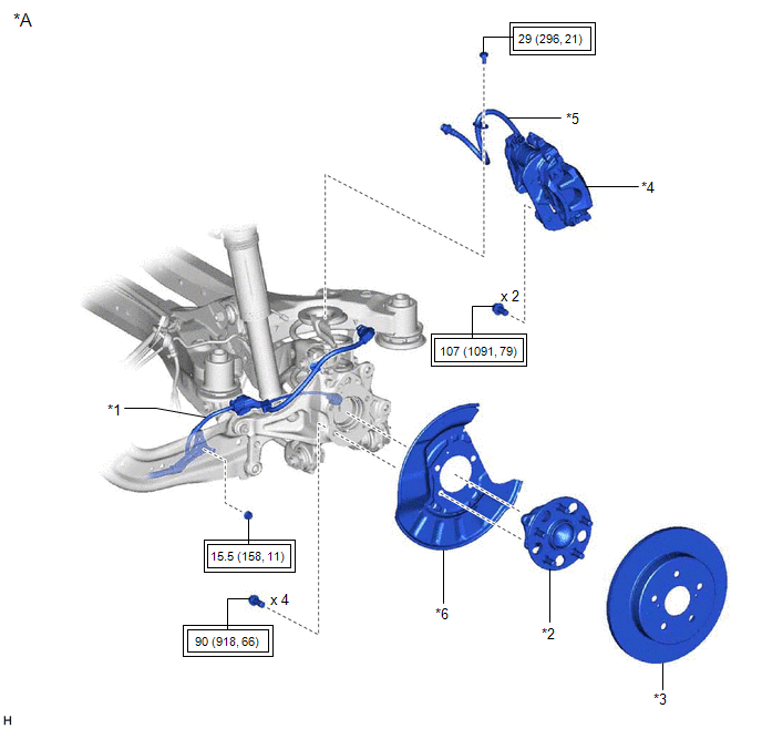
ILLUSTRATION
|
*A | w/o AVS |
- | - |
|
*1 | NO. 2 PARKING BRAKE WIRE ASSEMBLY |
*2 | REAR AXLE HUB AND BEARING ASSEMBLY |
|
*3 | REAR DISC |
*4 | REAR DISC BRAKE CALIPER ASSEMBLY |
|
*5 | REAR FLEXIBLE HOSE |
*6 | REAR DISC BRAKE DUST COVER SUB-ASSEMBLY |
 |
Tightening torque for "Major areas involving basic vehicle performance such as moving/turning/stopping": N*m (kgf*cm, ft.*lbf) |
- | - |
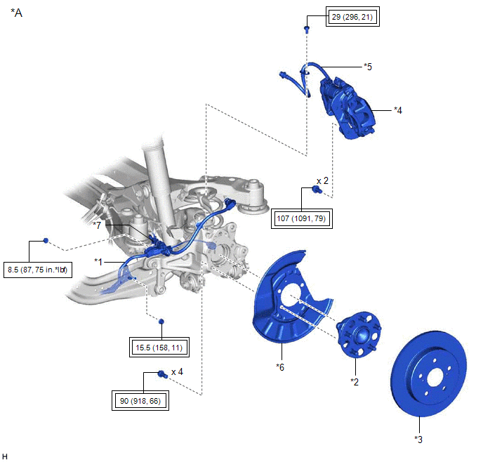
ILLUSTRATION
|
*A | w/ AVS |
- | - |
|
*1 | NO. 2 PARKING BRAKE WIRE ASSEMBLY |
*2 | REAR AXLE HUB AND BEARING ASSEMBLY |
|
*3 | REAR DISC |
*4 | REAR DISC BRAKE CALIPER ASSEMBLY |
|
*5 | REAR FLEXIBLE HOSE |
*6 | REAR DISC BRAKE DUST COVER SUB-ASSEMBLY |
|
*7 | WIRE HARNESS BRACKET |
- | - |
|
|
Tightening torque for "Major areas involving basic vehicle performance such as moving/turning/stopping": N*m (kgf*cm, ft.*lbf) |
|
N*m (kgf*cm, ft.*lbf): Specified torque |
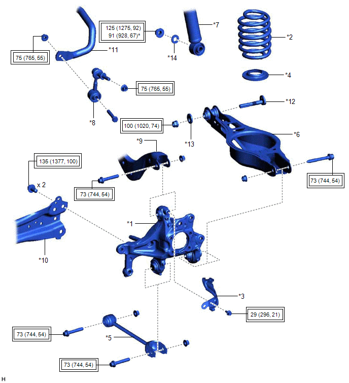
ILLUSTRATION
|
*1 | REAR AXLE CARRIER SUB-ASSEMBLY |
*2 | REAR COIL SPRING |
|
*3 | REAR FLEXIBLE HOSE BRACKET |
*4 | REAR LOWER COIL SPRING INSULATOR |
|
*5 | REAR NO. 1 SUSPENSION ARM ASSEMBLY |
*6 | REAR NO. 2 SUSPENSION ARM ASSEMBLY |
|
*7 | REAR SHOCK ABSORBER ASSEMBLY |
*8 | REAR STABILIZER LINK ASSEMBLY |
|
*9 | REAR UPPER CONTROL ARM ASSEMBLY |
*10 | REAR TRAILING ARM ASSEMBLY |
|
*11 | REAR STABILIZER BAR |
*12 | REAR SUSPENSION TOE ADJUST CAM SUB-ASSEMBLY |
|
*13 | NO. 2 CAMBER ADJUST CAM |
*14 | PLATE WASHER |
|
|
Tightening torque for "Major areas involving basic vehicle performance such as moving/turning/stopping": N*m (kgf*cm, ft.*lbf) |
* | For use with a ball joint lock nut wrench |
INSTALLATION
CAUTION / NOTICE / HINT
for HV Model:HINT:
PROCEDURE
1. TEMPORARILY INSTALL REAR AXLE CARRIER SUB-ASSEMBLY
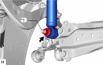
(a) Temporarily install the rear axle carrier sub-assembly to the rear shock absorber assembly with the nut and plate washer.
NOTICE:
Hold the rear axle carrier pin while rotating the nut.
| (b) Temporarily install the rear axle carrier sub-assembly to the rear upper control arm assembly with the bolt and nut. NOTICE:
|
|
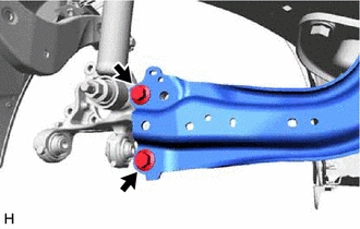
(c) Install the rear trailing arm assembly to the rear axle carrier sub-assembly with the 2 bolts.
Torque:
135 N·m {1377 kgf·cm, 100 ft·lbf}
2. INSTALL REAR FLEXIBLE HOSE BRACKET
(a) Install the rear flexible hose bracket to the rear axle carrier sub-assembly with the bolt.
Torque:
29 N·m {296 kgf·cm, 21 ft·lbf}
3. TEMPORARILY INSTALL REAR NO. 1 SUSPENSION ARM ASSEMBLY
Click here 
4. INSTALL REAR LOWER COIL SPRING INSULATOR
Click here
5. INSTALL REAR COIL SPRING
Click here
6. STABILIZE SUSPENSION
Click here
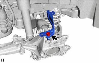
7. INSTALL REAR UPPER CONTROL ARM ASSEMBLY
(a) Install the rear upper control arm assembly to the rear axle carrier sub-assembly with the bolt.
Torque:
73 N·m {744 kgf·cm, 54 ft·lbf}
NOTICE:
Because the nut has its own stopper, do not turn the nut. Tighten the bolt with the nut secured.
8. INSTALL REAR NO. 1 SUSPENSION ARM ASSEMBLY
Click here
9. INSTALL REAR NO. 2 SUSPENSION ARM ASSEMBLY
(a) Install the rear No. 2 suspension arm assembly (rear axle carrier sub-assembly side) with the bolt.
Click here
10. INSTALL REAR SHOCK ABSORBER ASSEMBLY
Click here
11. INSTALL REAR STABILIZER LINK ASSEMBLY
Click here
12. INSTALL REAR AXLE HUB AND BEARING ASSEMBLY
Click here
13. INSTALL REAR DISC
Click here
14. INSTALL REAR DISC BRAKE CALIPER ASSEMBLY
Click here
15. INSTALL REAR FLEXIBLE HOSE
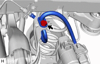
(a) Install the rear flexible hose to the rear flexible hose bracket with the bolt.
Torque:
29 N·m {296 kgf·cm, 21 ft·lbf}
16. INSTALL NO. 2 PARKING BRAKE WIRE ASSEMBLY (w/o AVS)
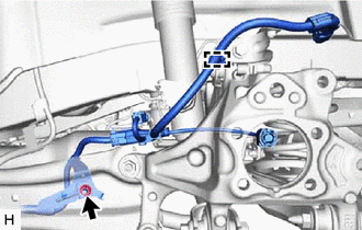
| (a) Install the No. 2 parking brake wire assembly to the rear trailing arm assembly with the nut. Torque: 15.5 N·m {158 kgf·cm, 11 ft·lbf} |
|
(b) Engage the 2 clamps.
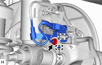
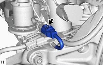
(c) Connect the No. 2 parking brake wire assembly connector to the parking brake actuator assembly.
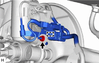
(d) Connect the No. 2 parking brake wire assembly connector to the rear axle hub and bearing assembly.
17. INSTALL NO. 2 PARKING BRAKE WIRE ASSEMBLY (w/ AVS)
| (a) Install the No. 2 parking brake wire assembly to the rear trailing arm assembly with the nut. Torque: 15.5 N·m {158 kgf·cm, 11 ft·lbf} |
|
(b) Engage the clamp.
|
(c) Engage the guide and install the wire harness bracket. |
|
(d) Install the nut.
Torque:
8.5 N·m {87 kgf·cm, 75 in·lbf}
(e) Engage the clamp and install the No. 2 parking brake wire assembly to the wire harness bracket.
| (f) Connect the connector. |
|
(g) Connect the No. 2 parking brake wire assembly connector to the parking brake actuator assembly.
(h) Connect the No. 2 parking brake wire assembly connector to the rear axle hub and bearing assembly.
18. INSTALL NO. 1 FLOOR UNDER COVER (for Gasoline Model)
(a) for RH Side:
Click here
19. INSTALL NO. 2 FLOOR UNDER COVER (for Gasoline Model)
(a) for LH Side:
Click here
20. INSTALL REAR WHEEL
Click here
21. INSTALL REAR NO. 2 SUSPENSION ARM ASSEMBLY
(a) Install the rear No. 2 suspension arm assembly (rear suspension member sub-assembly side) with the nut.
Click here
22. CONNECT CABLE TO NEGATIVE AUXILIARY BATTERY TERMINAL (for HV Model)
(a) Connect the reservoir level switch connector.
(b) Connect the cable to the negative (-) auxiliary battery terminal.
Click here
(c) Turn the power switch on (READY).
(d) Depress the brake pedal and release it.
(e) Clear the DTCs.
Click here
23. INSPECT AND ADJUST REAR WHEEL ALIGNMENT
Click here
24. CHECK FOR SPEED SENSOR SIGNAL
for HV Model: Click here
for Gasoline Model: Click here
25. PERFORM INITIALIZATION
for Gasoline Model:
|
|
|
Parking Assist Monitor System |
|
|
Panoramic View Monitor System |
|
|
|
|
Parking Assist Monitor System |
|
|
Panoramic View Monitor System |
|
REMOVAL
CAUTION / NOTICE / HINT
The necessary procedures (adjustment, calibration, initialization, or registration) that must be performed after parts are removed and installed, or replaced during rear axle carrier sub-assembly removal/installation are shown below.
Necessary Procedures After Parts Removed/Installed/Replaced (for Gasoline Model:)|
Replaced Part or Performed Procedure |
Necessary Procedure | Effect/Inoperative Function when Necessary Procedure not Performed |
Link |
|---|---|---|---|
| Rear wheel alignment adjustment |
Perform system variant learning and acceleration sensor zero point calibration. |
|
|
|
Suspension, tires, etc. (The vehicle height changes because of suspension or tire replacement.) |
|
|
|
|
Rear television camera assembly optical axis adjustment (Back camera position setting) |
Parking Assist Monitor System |
| |
| Panoramic View Monitor System |
|
|
Replaced Part or Performed Procedure |
Necessary Procedure | Effect/Inoperative Function when Necessary Procedure not Performed |
Link |
|---|---|---|---|
|
*: When performing learning using the Techstream.
Click here | |||
|
Auxiliary battery terminal is disconnected/reconnected |
Perform steering sensor zero point calibration |
Lane Departure Alert System (w/ Steering Control) |
|
|
Pre-collision System | |||
|
Intelligent Clearance Sonar System* | |||
|
Lighting System (for HV Model with Cornering Light) | |||
|
Memorize steering angle neutral point |
Parking Assist Monitor System |
| |
|
Panoramic View Monitor System |
| ||
|
Rear wheel alignment adjustment |
|
|
|
|
Suspension, tires, etc. (The vehicle height changes because of suspension or tire replacement.) |
|
|
|
|
Rear television camera assembly optical axis adjustment (Back camera position setting) |
Parking Assist Monitor System |
| |
| Panoramic View Monitor System |
| |
HINT:
PROCEDURE
1. PRECAUTION (for HV Model)
NOTICE:
After turning the power switch off, waiting time may be required before disconnecting the cable from the negative (-) auxiliary battery terminal. Therefore, make sure to read the disconnecting the cable from the negative (-) auxiliary battery terminal notices before proceeding with work.
Click here 
2. DISABLE BRAKE CONTROL (for HV Model)
Click here
3. REMOVE REAR WHEEL
Click here
4. REMOVE NO. 2 FLOOR UNDER COVER (for Gasoline Model)
(a) for LH Side:
Click here
5. REMOVE NO. 1 FLOOR UNDER COVER (for Gasoline Model)
(a) for RH Side:
Click here
6. SEPARATE NO. 2 PARKING BRAKE WIRE ASSEMBLY (w/o AVS)
| (a) Disconnect the No. 2 parking brake wire assembly connector from the parking brake actuator assembly. NOTICE:
|
|
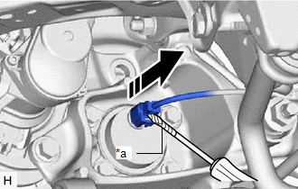
| (b) Using a screwdriver with its tip wrapped with protective tape, disconnect the No. 2 parking brake wire assembly connector from the rear axle hub and bearing assembly. NOTICE: Be careful not to damage the rear axle hub and bearing assembly or connector cover. |
|
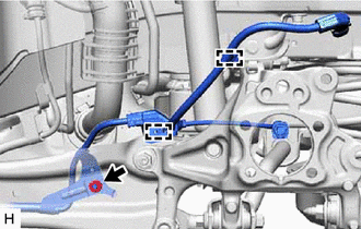
| (c) Remove the nut, disengage the 2 clamps and separate the No. 2 parking brake wire assembly from the rear flexible hose bracket and rear trailing arm assembly. |
|
7. SEPARATE NO. 2 PARKING BRAKE WIRE ASSEMBLY (w/ AVS)
| (a) Disconnect the No. 2 parking brake wire assembly connector from the parking brake actuator assembly. NOTICE:
|
|
| (b) Using a screwdriver with its tip wrapped with protective tape, disconnect the No. 2 parking brake wire assembly connector from the rear axle hub and bearing assembly. NOTICE: Be careful not to damage the rear axle hub and bearing assembly or connector cover. |
|
| (c) Disconnect the connector. |
|
| (d) Remove the nut and disengage the clamp. |
|
| (e) Remove the nut, disengage the clamp and separate the No. 2 parking brake wire assembly from the rear flexible hose bracket and rear trailing arm assembly. |
|
8. SEPARATE REAR FLEXIBLE HOSE
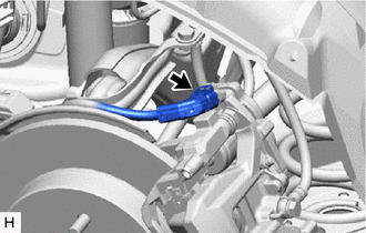
| (a) Remove the bolt and separate the rear flexible hose from the rear flexible hose bracket. |
|
9. SEPARATE REAR DISC BRAKE CALIPER ASSEMBLY
Click here
10. REMOVE REAR DISC
Click here
11. REMOVE REAR AXLE HUB AND BEARING ASSEMBLY
Click here
12. REMOVE REAR FLEXIBLE HOSE BRACKET
| (a) Remove the bolt and rear flexible hose bracket from the rear axle carrier sub-assembly. |
|
13. REMOVE REAR STABILIZER LINK ASSEMBLY
Click here
14. REMOVE REAR COIL SPRING
Click here
15. REMOVE REAR LOWER COIL SPRING INSULATOR
Click here
16. REMOVE REAR NO. 1 SUSPENSION ARM ASSEMBLY
Click here
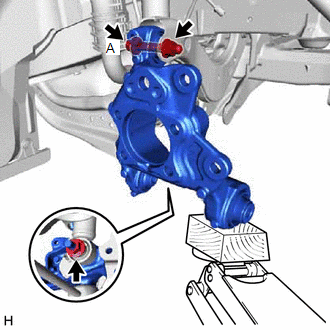
17. REMOVE REAR AXLE CARRIER SUB-ASSEMBLY
| (a) Loosen the 2 bolts of the rear trailing arm assembly. |
|
| (b) Loosen the nut of the rear shock absorber assembly. NOTICE: Hold the rear axle carrier pin while rotating the nut. |
|
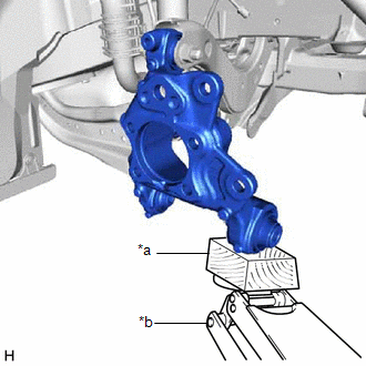
| (c) Using a jack and wooden block, support the rear axle carrier sub-assembly. NOTICE:
|
|
| (d) Loosen the bolt (A). NOTICE: Because the nut has its own stopper, do not turn the nut. Loosen the bolt with the nut secured. |
|
(e) Remove the 2 bolts and separate the rear trailing arm assembly from the rear axle carrier sub-assembly.
(f) Remove the nut and plate washer, and separate the rear shock absorber assembly from the rear axle carrier sub-assembly.
NOTICE:
Hold the rear axle carrier pin while rotating the nut.
(g) Remove the bolt (A), nut and rear axle carrier sub-assembly from the rear upper control arm assembly.
NOTICE:
Because the nut has its own stopper, do not turn the nut. Loosen the bolt with the nut secured.
Toyota Avalon (XX50) 2019-2022 Service & Repair Manual > Electronically Controlled Brake System(for Gasoline Model): Brake Actuator Operation Sound is Loud during Initial Check. Brake Hold Operated Indicator Light Circuit. Brake Hold Standby Indicator Light Circuit
Brake Actuator Operation Sound is Loud during Initial Check CAUTION / NOTICE / HINT NOTICE: When replacing the skid control ECU (brake actuator assembly), perform system variant learning and acceleration sensor zero point calibration. Click here PROCEDURE 1. PERFORM ROAD TEST (a) After turning the e ...